Water cooling device with heat exchange pipe

A technology of water cooling devices and heat exchange tubes, applied in the direction of heat exchanger types, indirect heat exchangers, fixed conduit components, etc., can solve the problems of insufficient energy utilization efficiency, achieve a high degree of follow-up development, wide range of uses, and flexible applications Effect

Inactive Publication Date: 2011-04-27
秦宇献
View PDF7 Cites 0 Cited by
  • Summary
  • Abstract
  • Description
  • Claims
  • Application Information

AI Technical Summary

Problems solved by technology

However, the above-mentioned structure does not use the heat energy brought by some high-temperature water flow, but directly dissipates the heat energy into the air. The energy utilization efficiency is not high enough, and some other low-temperature or high-temperature heat-conducting media cannot be introduced for heat exchange. Therefore the inventor has made improvement to above-mentioned structure

Method used


Image

  • Water cooling device with heat exchange pipe
  • Water cooling device with heat exchange pipe

Examples


Embodiment Construction

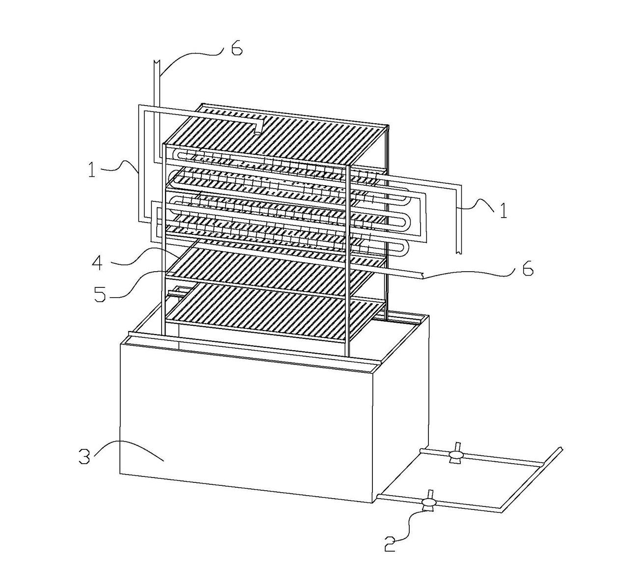
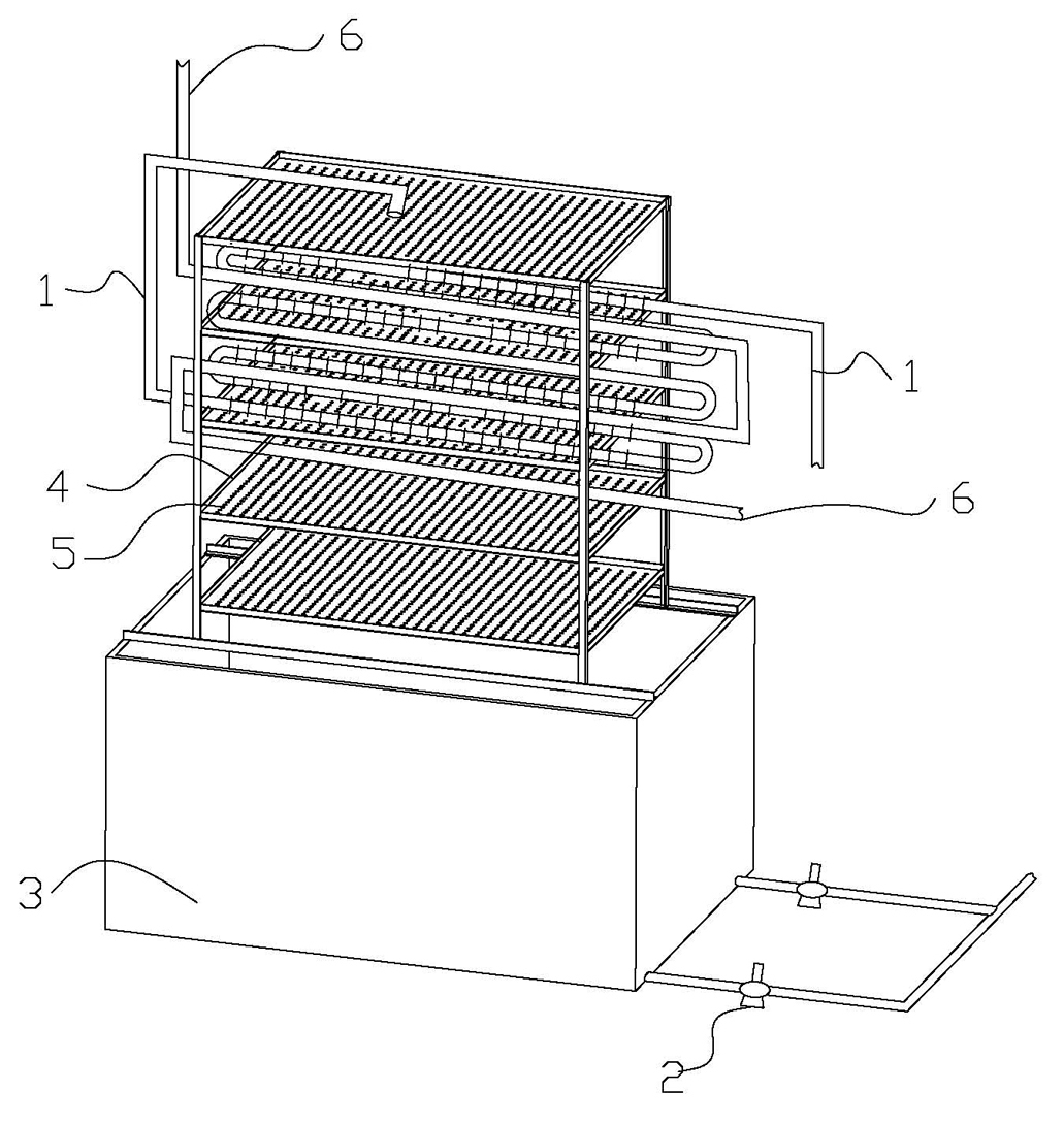
[0011] refer to figure 1 , the present invention discloses a water cooling device with heat exchange pipes, which includes a cooling pipe 1, a water pump 2, a water tank 3 and several layers of cooling plates 4 with drainage holes 5 installed above the water tank 3, the inlet of the water pump 2 The water outlet is connected to the water tank 3 through a water pipe, the water inlet of the cooling pipe 1 is connected to the hot water inflow end, and the water outlet of the cooling pipe 1 is located on the uppermost heat dissipation plate 4, so that the water coming out of the cooling pipe 1 It flows into the uppermost heat dissipation plate 4, which also includes a heat exchange tube 6 and a heat transfer medium. The heat transfer medium flows in from the inlet of the heat exchange tube 6 and flows out from the outlet of the heat exchange tube 6. 1 are arranged in parallel, and can exchange heat energy with the cooling row pipe 1 through the heat transfer medium.

[0012] As s...


PUM


Abstract

The invention discloses a water cooling device with a heat exchange pipe, which comprises a cooling grid, a water pump, a water tank, and a plurality of layers of cooling plates, wherein the cooling plates are arranged above the water tank and provided with drain holes; a water inlet of the water pump is connected with the water tank by a water pipe; a water inlet of the cooling grid is connected with a hot-water feed end; and a water outlet of the cooling grid is arranged on the top cooling plate, so that the water discharged from the cooling grid flows into the top cooling plate. The water cooling device in the invention is characterized in that the water cooling device also comprises a heat exchange pipe and a heat-conducting medium, the heat exchange pipe and the cooling grid are arranged in parallel, and the water cooling device in the invention carries out heat exchange with external facilities and the cooling grid through the heat exchange pipe and the heat-conducting medium. Because of adopting the structure above, the water cooling device in the invention has the advantages of wide use, flexible application, and high subsequent development degree.

Description

technical field [0001] The invention relates to a water cooling device, in particular to a water cooling device with heat exchange tubes. Background technique [0002] With the development of modern industry, the power requirements for various large-scale machines are getting higher and higher, but it also brings the problems of high machine temperature and difficult heat dissipation. Although there are many cooling measures, such as directly using fan blowing for air cooling, the heat dissipation is slow and the effect is not good; the direct flushing cooling method is effective, but most machines cannot directly contact water, so the scope of use of this method is narrow. Moreover, the waste of water is serious; there is also a compressor to compress the refrigerant, and the refrigerant flows through the heat pipe installed in the machine to take away heat, but this method has a high cost, and the operation of the compressor also consumes a large amount of energy. [0003...

Claims


Application Information

Patent Timeline
Patent Type & Authority Applications(China)
IPC IPC(8): F28D3/02F28D5/02
Inventor 秦宇献
Owner 秦宇献
Why Eureka
Try Eureka