Abnormity diagnosis equipment for crank angle sensor

A technology of crank angle sensor and abnormal diagnosis, which is applied in the direction of mechanical equipment, conversion sensor output, electrical control, etc., and can solve problems such as damage to the engine and deterioration of the working state of the engine

Inactive Publication Date: 2011-04-27
TOYOTA JIDOSHA KK
View PDF6 Cites 13 Cited by
  • Summary
  • Abstract
  • Description
  • Claims
  • Application Information

AI Technical Summary

Problems solved by technology

As a result, engine performance deteriorates and in the worst case may damage the engine

Method used


Image

  • Abnormity diagnosis equipment for crank angle sensor
  • Abnormity diagnosis equipment for crank angle sensor
  • Abnormity diagnosis equipment for crank angle sensor

Examples


Embodiment Construction

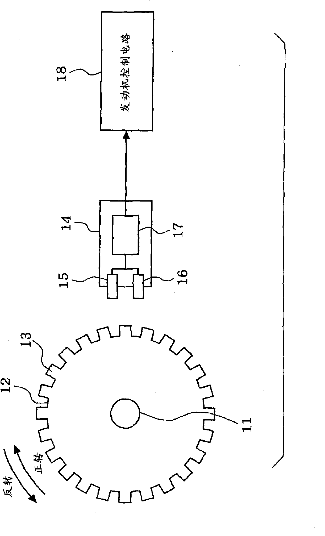
[0028] Hereinafter, embodiments of the present invention will be described with reference to the drawings. First, refer to figure 1 The configuration of the crank angle sensing system according to this embodiment will be described.

[0029]A disc-shaped signal rotor 12 is fixed to a crankshaft 11 of an engine (internal combustion engine). A plurality of protrusions 13 are formed on the outer edge portion of the signal rotor 12 at a predetermined crank angle pitch (for example, at a 10CA (crank angle) pitch). A crank angle sensor 14 is fixed to the engine side facing the outer edge portion of the signal rotor 12 . The crank angle sensor 14 has a first sensor 15 (sensor portion) and a second sensor 16 (sensor portion) arranged along the outer edge portion of the signal rotor 12 at predetermined crank angle intervals.

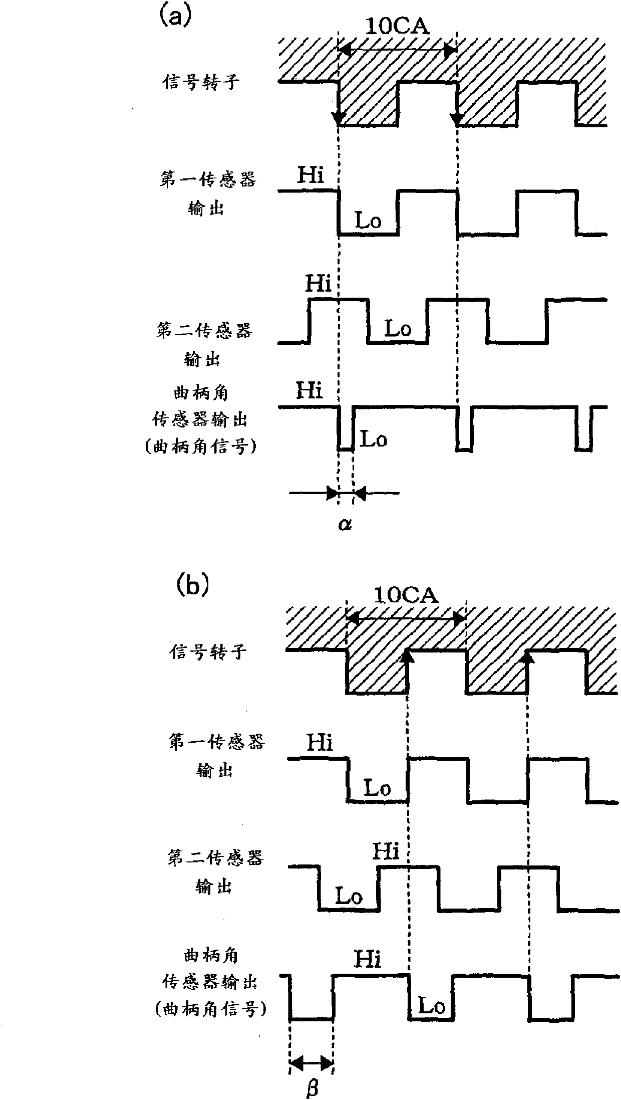
[0030] The sensors 15 , 16 are, for example, electromagnetic induction sensors, Hall sensors or the like. Such as figure 2 As shown, when the protrusion 13 ...


PUM


Abstract

The crank angle sensor (14) herein comprises a first sensor (15) and a second sensor (16) which are disposed along the circumference of the rim of a signal rotor (12), and determines rotating direction of a crankshaft (11) based on relationship of the outputs of the two sensors (15, 16). The crank angle sensor (14) outputs crank angle signals of different pulse widths in accordance to rotation directions to an engine control circuit (18). The engine control circuit (18) measures the time required by a predetermined number of crank angle signals output by the crank angle sensor (14), the time being seen as predetermined crank angle time. The engine control circuit (18) determines the presence or absence of abnormity of the crank angle sensor (14) by comparing whether the current predetermined crank angle time the previous predetermined crank angle time (or the predetermined crank angle time before the previous predetermined crank angle time) fluctuates at the predetermined value or alarge value.

Description

technical field [0001] The present invention relates to an abnormality diagnosis device of a crank angle sensing system having a crank angle sensor capable of detecting reverse rotation of a crankshaft of an internal combustion engine. Background technique [0002] Generally, during operation of an internal combustion engine, ignition control and fuel injection control are performed by identifying a cylinder and sensing a crank angle by output signals based on a crank angle sensor and a cam wrap angle sensor. However, during starting of the internal combustion engine, until the crank of the internal combustion engine is turned by the starter and the identification of the specific cylinder is completed, that is, until the signal of the predetermined crank angle of the specific cylinder is detected, the cylinder to perform ignition and injection first is not known. [0003] Therefore, there is a conventional technique of storing in a memory the crank angle at which the rotatio...

Claims


Application Information

Patent Timeline
Patent Type & Authority Applications(China)
IPC IPC(8): G01B7/30F02D45/00
CPCG01D5/24461
Inventor 枡田哲内田晶人中村良文吉原正朝
Owner TOYOTA JIDOSHA KK
Why Eureka
Try Eureka