
Optical pickup device

A technology of optical pick-up and laser, which is applied in the direction of beam guiding device, optical detector, optical recording head, etc., can solve the problems of detection signal deterioration, bad influence of focus servo and tracking servo, etc., and achieve the effect of suppressing stray light and simple structure

Inactive Publication Date: 2011-04-27
SANYO ELECTRIC CO LTD
View PDF3 Cites 1 Cited by
  • Summary
  • Abstract
  • Description
  • Claims
  • Application Information

AI Technical Summary

Problems solved by technology

Therefore, if unwanted reflected light (stray light) enters the photodetector from the recording layers above and below the target recording layer, the detection signal will deteriorate, which may adversely affect the focus servo and tracking servo.

Method used


Image

  • Optical pickup device
  • Optical pickup device
  • Optical pickup device

Examples


Embodiment Construction

[0036] Hereinafter, embodiments of the present invention will be described with reference to the drawings.

[0037]

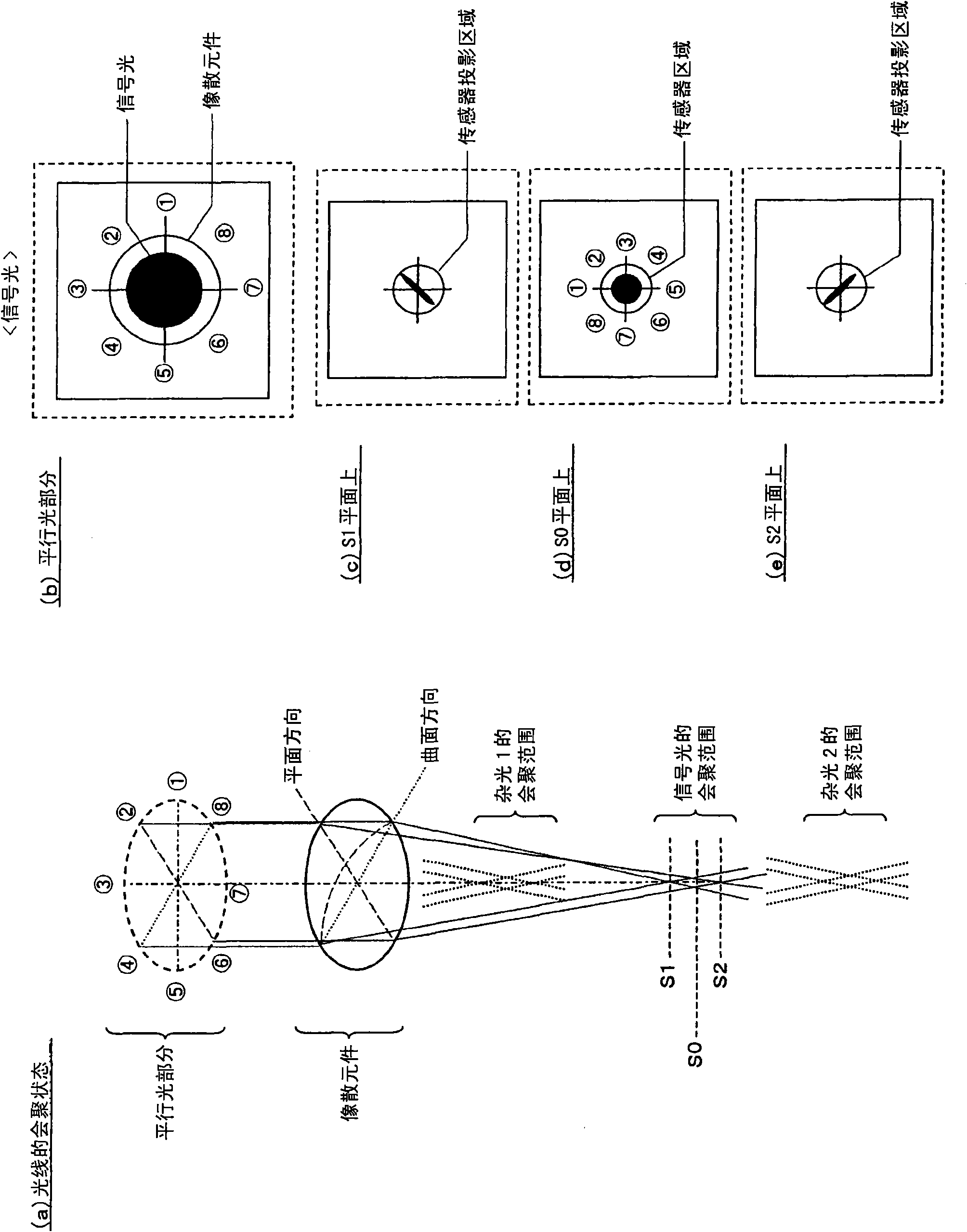
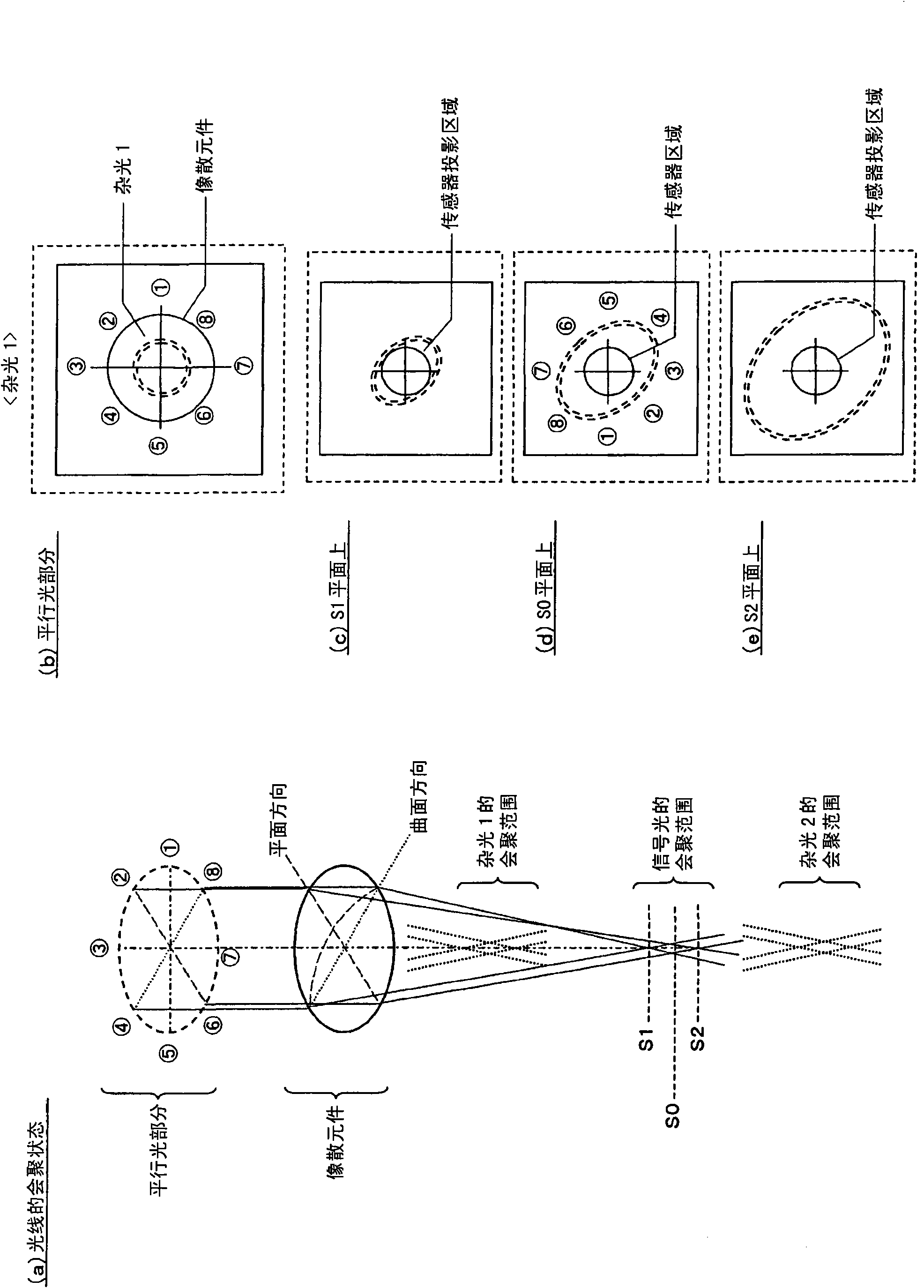
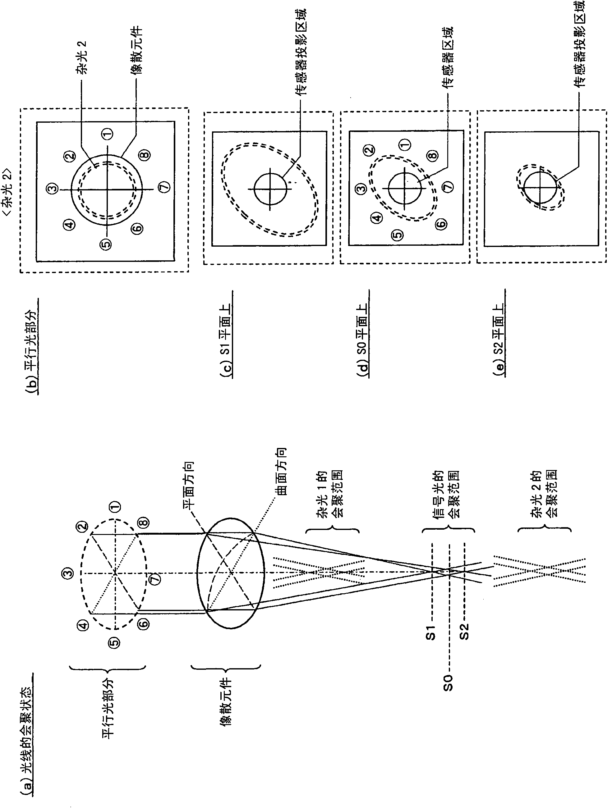
[0038] First, refer to Figure 1 to Figure 10 , to describe the technical principle applied in this embodiment. In addition, here, assume a case where laser light is irradiated to a recording medium in which a plurality of recording layers are arranged in a stacking direction. Hereinafter, among the plurality of recording layers, the recording layer on which the laser light converges is referred to as a "target recording layer".

[0039] figure 1 (a) is a diagram showing a converging state of signal light and stray light when laser light (signal light) reflected from a target recording layer enters an astigmatic element such as an anamorphic lens (anamorens) in a parallel light state. In addition, "stray light 1" is the laser light reflected from the recording layer located one layer behind the target recording layer when viewed from the laser incident sid...


PUM


Abstract

The invention provides an optical pickup device which has a simple structure and is capable of effectively inhibiting compatibility of stray light. BD light or CD light reflected by BD or CD is imparted to astigmatism by a detection lens (109). Then, in the BD light or the CD light, light beams in four light beam areas disposed at the periphery of a laser optical axis pass through a spectral element (110) and are separated from one another due to the diffraction effect. A detection surface of a photodetector is provided with sensors (P21-P28) for receiving the BD light and sensors (P31-P38) for receiving the CD light. DVD light is divided into three light beams by a diffraction grating (102) and is radiated to DVD. The DVD light reflected by the DVD is received by sensors (P41-P43) in such a manner that the DVD light is not separated by the spectral element (110). A gap G2 between laser elements in a semiconductor laser (101) is set depending on the spacing S1 between sensor patterns.

Description

technical field [0001] The present invention relates to an optical pickup device, and is particularly suitable for use when irradiating laser beams of different wavelengths to a recording medium in which a plurality of recording layers are stacked. Background technique [0002] In recent years, along with the increase in the capacity of optical discs, multi-layer recording layers are progressing. By including multiple recording layers in one optical disc, the data capacity of the optical disc can be significantly increased. When stacking recording layers, conventionally, two layers were generally used on one side, but recently, in order to further increase the capacity, it is also considered to arrange three or more recording layers on one side. Here, if the number of stacked recording layers is increased, the capacity of the optical disk can be increased. However, the pitch between recording layers becomes narrower, and signal degradation due to interlayer crosstalk incre...

Claims


Application Information

Patent Timeline
Patent Type & Authority Applications(China)
IPC IPC(8): G11B7/135
CPCG11B7/1353G11B7/13922G11B7/131G11B2007/0006G11B7/0912
Inventor 永富谦司
Owner SANYO ELECTRIC CO LTD
Learn More