
Method for transmitting monitoring videos in real time in broadband digital clustering communication system

A technology of digital trunking communication and monitoring video, applied in the field of communication, can solve problems such as inability to provide broadband multimedia services, real-time transmission of monitoring video, and low delay

Active Publication Date: 2011-04-27
POTEVIO INFORMATION TECH
View PDF3 Cites 42 Cited by
  • Summary
  • Abstract
  • Description
  • Claims
  • Application Information

AI Technical Summary

Problems solved by technology

However, with the advancement of information technology and the vigorous development of Internet applications, the business requirements of trunking users in various industries, enterprise users, and government departments for digital trunking communication systems are gradually shifting from ordinary dispatching voice to integrating voice, data, image and The direction of broadband multimedia integrating video is changing. It is hoped that the broadband digital trunking communication system with high speed, low delay, and quality of service (QoS) can be used to improve work efficiency and speed up informatization construction. However, the existing digital trunking communication system is still Unable to provide real-time transmission of broadband multimedia services, surveillance video, etc.

Method used


Image

  • Method for transmitting monitoring videos in real time in broadband digital clustering communication system
  • Method for transmitting monitoring videos in real time in broadband digital clustering communication system
  • Method for transmitting monitoring videos in real time in broadband digital clustering communication system

Examples


Embodiment 1

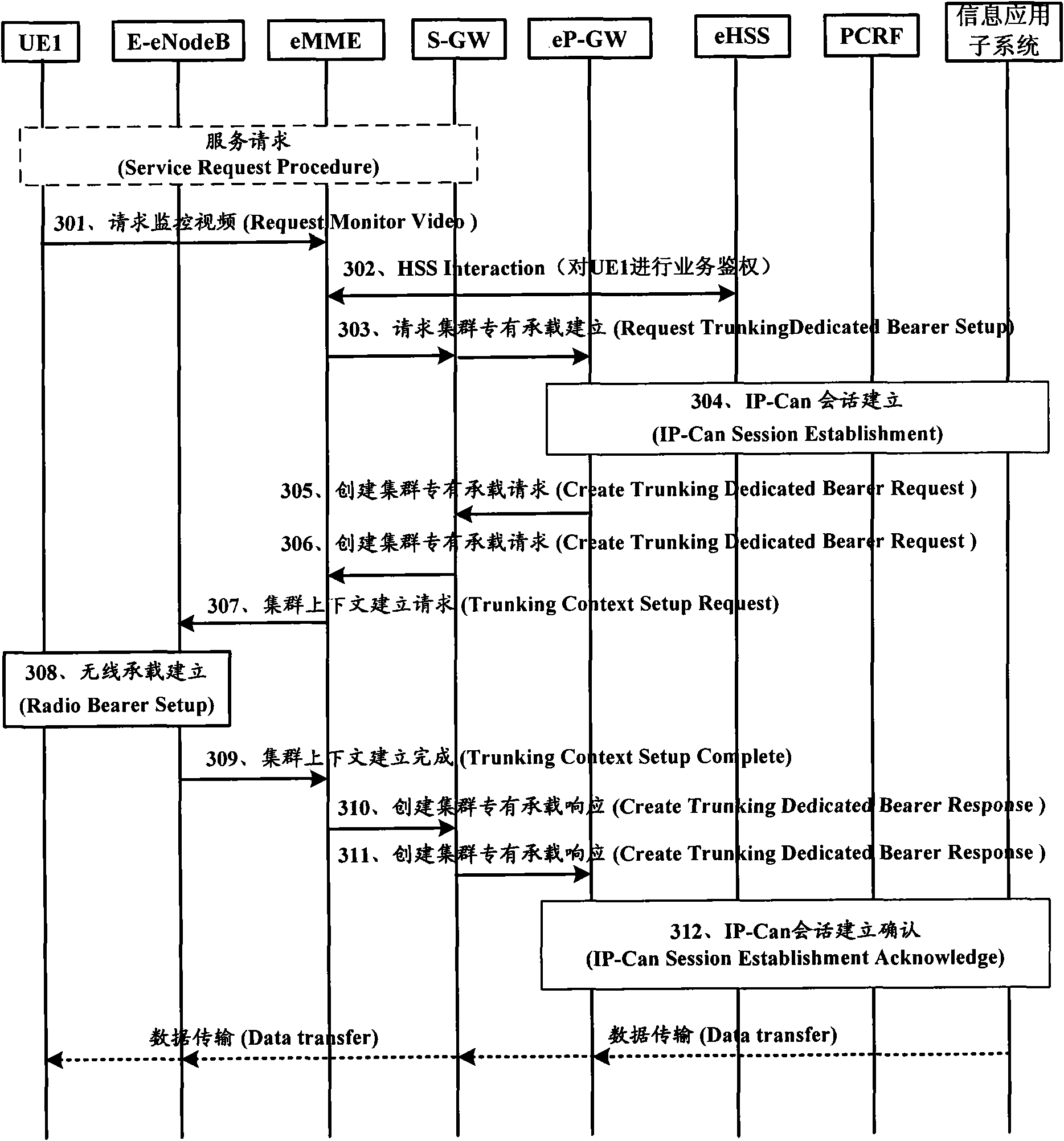
[0122] Embodiment 1, the user terminal actively initiates a service request, requesting the network to deliver a specific surveillance video.

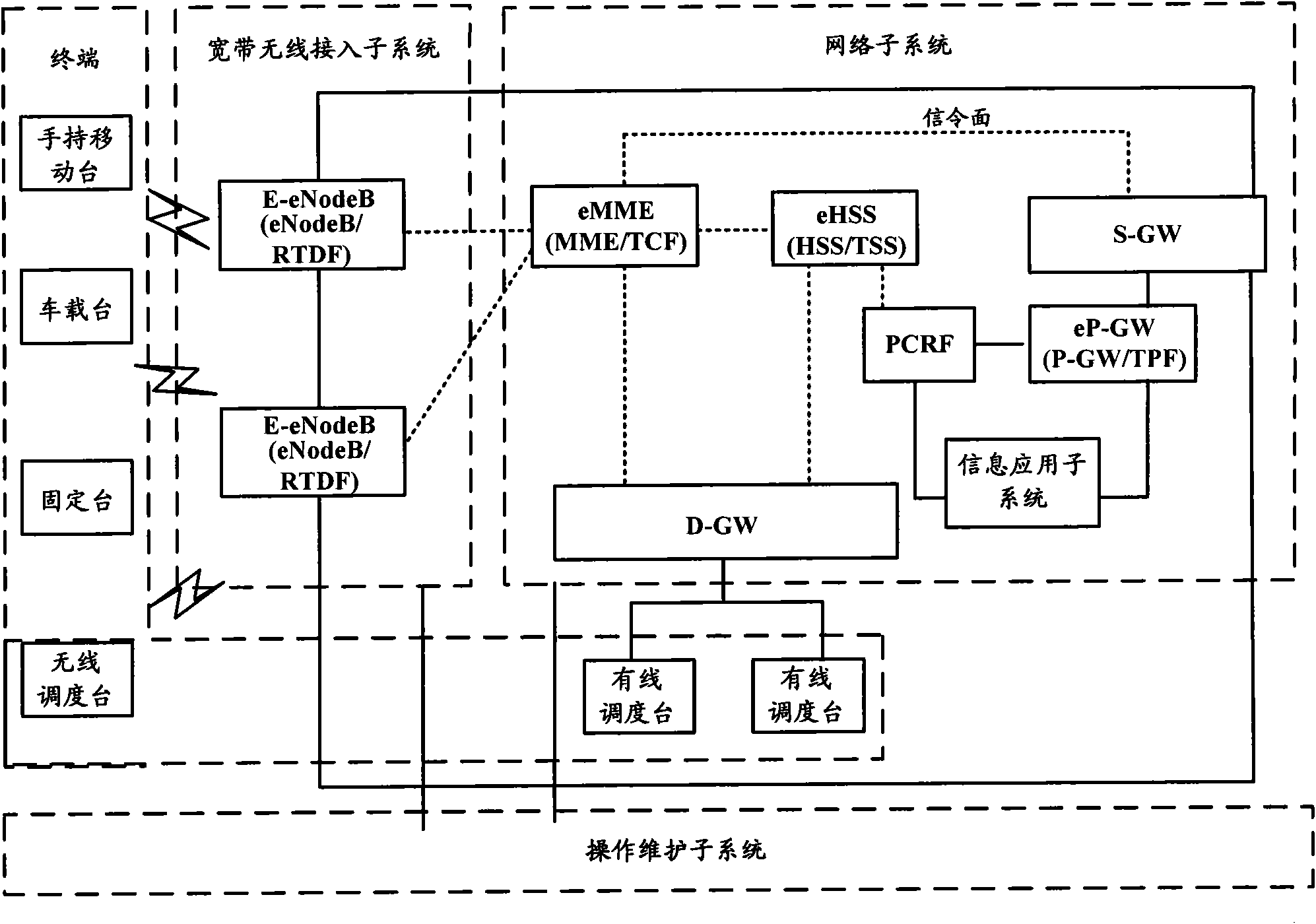
[0123] Such as image 3 As shown, the user terminal sends a video request message to the eMME through the NAS message; the eMME interacts with the eHSS in the network subsystem to perform service authentication on the user terminal; if the authentication passes, the eMME sends the message to the eP-GW through the S-GW Request Trunking Dedicated Bearer Setup (RequestTrunking Dedicated Bearer Setup) message; eP-GW, eHSS, PCRF in the network subsystem interact with the information application subsystem to obtain the QoS information required for the service, and initiate cluster dedicated bearer setup based on this QoS information. Bearer establishment. Specifically include the following steps:

[0124] Steps 301 to 302 are specific procedures for a user terminal registered in the trunking communication system to send a request for a sur...

Embodiment 2

[0142] In the second embodiment, the cable dispatching station requests to deliver surveillance video to a designated group or designated user terminal.

[0143] Compared with the implementation process in which the user terminal actively requests surveillance video, this service is initiated by the cable dispatching station. The wired dispatcher sends the message of requesting surveillance video to eMME through the dispatching gateway, notifying it to send the surveillance video for the specified user terminal; then, eMME sends a message requesting cluster-specific bearer establishment to eP-GW through S-GW; eP-GW and PCRF Perform signaling interaction with the information application subsystem to obtain the QoS information required by the service, and initiate the establishment of a cluster-specific bearer based on the QoS information. The specific implementation process is attached Figure 4 shown, including the following steps:

[0144] Steps 401 to 403 are specific proc...

Embodiment 3

[0163] Embodiment 3, the wireless dispatching station requests to send surveillance video to a designated group or a designated user terminal.

[0164] The cable dispatcher can follow the following steps: Figure 4 The specific steps shown realize the transmission of the surveillance video service data flow. The specific steps of the wireless dispatching station to realize the transmission of monitoring video service data streams are different from the wired dispatching station in that the wireless dispatching station sends a request for monitoring video messages to the eMME through the E-eNodeB in the broadband wireless access subsystem, such as Figure 5 shown.

[0165] Steps 501 to 502 are specific procedures for the wireless dispatcher to send a video request message to the eMME.

[0166] Step 501, the wireless dispatcher sends a request monitor video (RequestMonitor Video) message to the eMME through the E-eNodeB, and the message includes dispatcher identification, desi...


PUM


Abstract

The invention relates to a method for transmitting monitoring videos in real time in a broadband digital clustering communication system, which comprises the following steps: a terminal sends a monitoring video request message to a network subsystem; the network subsystem authenticates the terminal, interacts with an information application subsystem to generate quality of service (QoS) policies,and allocates clustering specially-loaded QoS parameters; the network subsystem sends the clustering specially-loaded QoS parameters to a broadband wireless access subsystem, and the broadband wireless access subsystem allocates downlink resources and sends the downlink resources to the user terminal; the user terminal completes the configuration of each layer according to the description of the downlink resources; the broadband wireless access subsystem sends clustering contexts to the network subsystem to establish a completion message; and the information application subsystem interacts with the network subsystem and sends business data streams of the monitoring videos to the user terminal through the network subsystem and the broadband wireless access subsystem. After the embodiment of the invention is applied, the high rate and low time delay of real-time transmission of the monitoring videos can be guaranteed, thereby providing the QoS guarantee.

Description

technical field [0001] The present invention relates to the field of communication technology, more specifically, to a method for real-time transmission of monitoring video in a broadband digital trunking communication system based on Time Division Long Term Evolution (TD-LTE, Time Division-Long Term Evolution) technology. Background technique [0002] The digital trunking communication system is a mobile command and dispatch system, which plays a huge role in the field of professional communication. Compared with the public mobile communication system, the digital trunking communication system supports private calls and group calls, and the call connection is fast, and the users in the group share the downlink business channel, which has a high spectrum utilization rate. [0003] Due to its unique characteristics of dispatching, group calling and fast calling, the digital trunking communication system has played a huge role in the field of professional communication. Since...

Claims


Application Information

Patent Timeline
Patent Type & Authority Applications(China)
IPC IPC(8): H04W4/10H04W12/06H04W72/12H04N7/18H04W12/71
Inventor 潘松刘博张洁许玮蔡杰蒋纯波汤素锋李瑞林
Owner POTEVIO INFORMATION TECH
Learn More