Sensor type door lamp control switch

A technology for controlling switches and sensors, applied in the field of sensor-type door light control switches, can solve the problems of mechanical wear of buttons, ineffective light bulbs, and shortened service life.

Inactive Publication Date: 2011-04-27
HAMLIN ELECTRONIC (SUZHOU) CO LTD
View PDF7 Cites 1 Cited by
  • Summary
  • Abstract
  • Description
  • Claims
  • Application Information

AI Technical Summary

Problems solved by technology

[0002] A kind of patent No. 94227773.2 disclosed on the market is a touch bridge door light switch, which is composed of a terminal, a touch bridge, a compression spring, a pressing key and a riveted silver contact. When the door is opened, the pressing key is not pressed down. At this time, the switch is turned on through the contact bridge, the external light circuit is turned on, and the bulb plays the role of lighting; when the door is closed and the button is pressed, the touch bridge is disconnected from the terminal, the external circuit is disconnected, and the bulb does not provide lighting. In this way, when controlling each light switch, you have to press the trigger button, and the mechanical wear of the button will occur after a long time, reducing its service life

Method used


Image

  • Sensor type door lamp control switch
  • Sensor type door lamp control switch
  • Sensor type door lamp control switch

Examples


Embodiment Construction

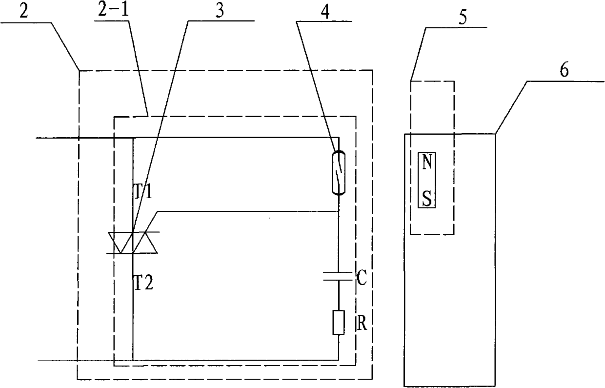
[0014] figure 1 A sensor-type door light control switch is shown, which includes a sensor 2 and a trigger magnet 5 respectively arranged on two relatively movable components. There is a sensor circuit 2-1 in the sensor 2, and the sensor circuit 2-1 includes A normally open dry reed switch 4 as a sensing element and a bidirectional thyristor 3 for turning on and off the lighting circuit, the normally open dry reed switch 4 is connected between the T1 pole and the gate pole of the triac 3 . A normally open dry reed switch 4 is added to the sensor 2 as a sensitive element, and the normally open dry reed switch 4 can realize billions of operations under the condition of low voltage logic load.

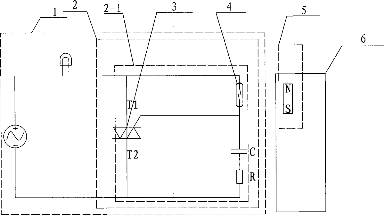
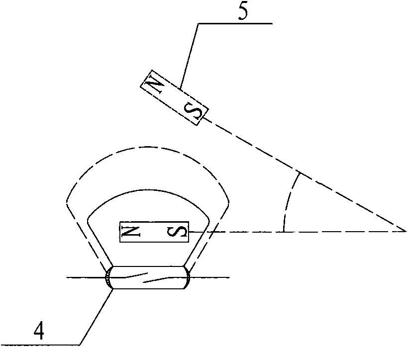
[0015] figure 2 The sensor-type door light control switch shown is used in the lighting circuit of household appliances such as refrigerators, freezers, refrigerators, freezers, and disinfection cabinets. The trigger magnet 5 of the tube 4 is installed on the inner side of the box door ...


PUM


Abstract

The invention relates to a sensor type door lamp control switch which is characterized by comprising a sensor and a trigger magnet. The sensor and the trigger magnet are respectively arranged on two relatively moving members; a sensor circuit is arranged in the sensor and comprises a normally open reed switch used as a sensing element, a bidirectional thyristor for controlling the ON and OFF of a lighting circuit, and a capacitance-type resistor; the normally open reed switch is connected between a T1 pole and a gate pole of the bidirectional thyristor; the members are a box body and a box door; the sensor is fixed to the open periphery of the box body; and the trigger magnet for controlling the ON and OFF of the normally open reed switch is arranged at the corresponding position on the inner side of the box door. The reed switch and the capacitance-type resistor form a control loop, when the trigger magnet approaches to the sensor, the normally open reed switch is closed, the bidirectional thyristor is switch off due to no trigger signals coming from the gate pole, the lighting circuit is off, and thus, the non-contact type control of the door lamp is completed, the mechanical wear of a switch key is reduced, and the service life of the control switch is prolonged.

Description

technical field [0001] The invention relates to a trigger-type controllable switch, in particular to a sensor-type door light control switch which can be controlled by a magnetic field and can avoid mechanical abrasion of keys. Background technique [0002] A kind of patent No. 94227773.2 disclosed on the market is a touch bridge door light switch, which is composed of a terminal, a touch bridge, a compression spring, a pressing key and a riveted silver contact. When the door is opened, the pressing key is not pressed down. At this time, the switch is turned on through the contact bridge, the external light circuit is turned on, and the bulb plays the role of lighting; when the door is closed and the button is pressed, the touch bridge is disconnected from the terminal, the external circuit is disconnected, and the bulb does not provide lighting. Effect, like this, when controlling each light switch, all must press trigger button, the mechanical wear and tear of button just ...

Claims


Application Information

Patent Timeline
Patent Type & Authority Applications(China)
IPC IPC(8): H05B37/02H03K17/72
Inventor 吕海涛史大勇
Owner HAMLIN ELECTRONIC (SUZHOU) CO LTD
Why Eureka
Try Eureka