Space-coding parallel excitation system and method

A technology of spatial encoding and excitation system, applied in the field of optical molecular imaging, can solve the problems of inaccuracy, incomplete fluorescence image information, increased imaging time, etc. Effect

Inactive Publication Date: 2011-04-27
TSINGHUA UNIV
View PDF6 Cites 4 Cited by
  • Summary
  • Abstract
  • Description
  • Claims
  • Application Information

AI Technical Summary

Problems solved by technology

[0003] However, under the excitation method of the traditional single-point light source, fluorescence imaging can only obtain the local fluorescence information near the position where the excitation light source can be irradiated, while the fluorescent markers in the area far away from the excitation light source cannot be excited or over-excited. Weak, which leads to incomplete and inaccurate fluorescence image information obtained
Although the fluorescence information of different parts can be obtained by continuously changing the position of the excitation light source several times, this will greatly increase the structural complexity of the imaging system, and the imaging time will also be doubled
In practical applications, it is often necessary to observe various fluorescent signals with different temporal and spatial distribution characteristics, especially some fast and dynamic fluorescent signals, and the excitation method of the traditional single-point light source cannot meet the demand

Method used


Image

  • Space-coding parallel excitation system and method
  • Space-coding parallel excitation system and method
  • Space-coding parallel excitation system and method

Examples


Embodiment Construction

[0013] The present invention will be described in detail below in conjunction with the accompanying drawings and embodiments.

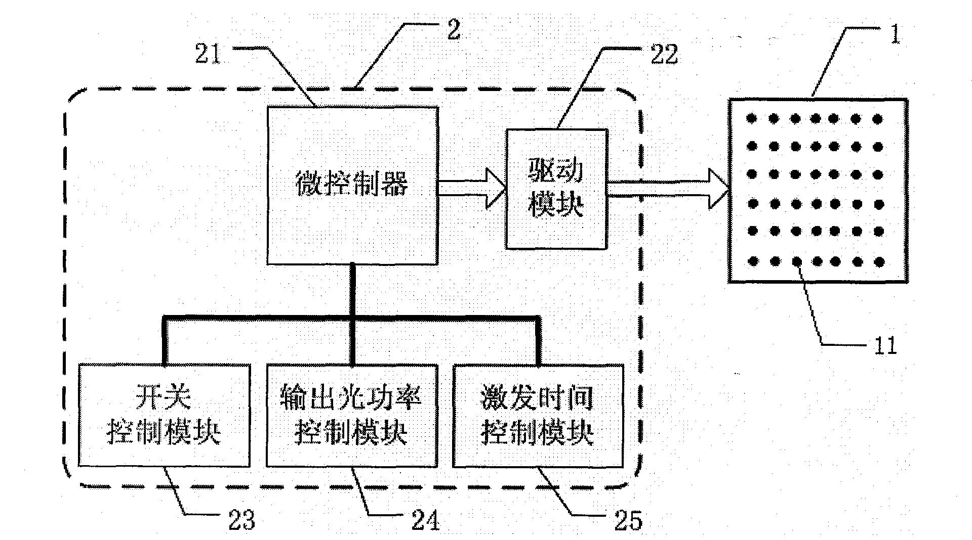
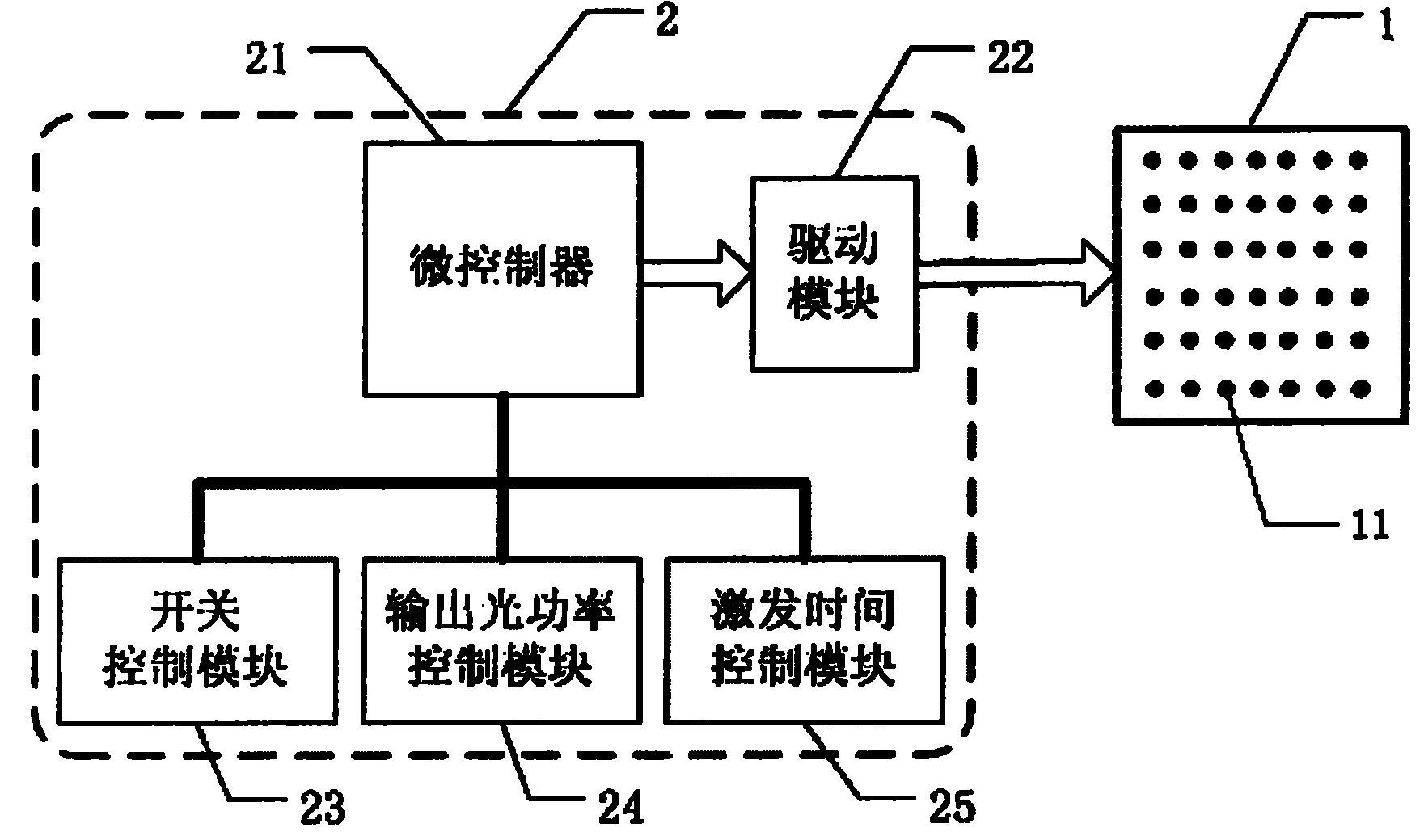
[0014] Such as figure 1 As shown, the present invention includes a parallel excitation array 1 and a spatial encoding control system 2 .

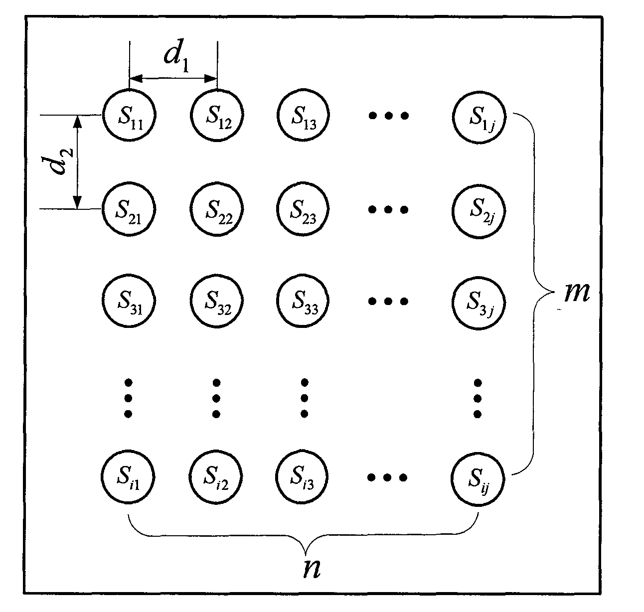
[0015] Such as figure 2 As shown, the parallel excitation array 1 includes several single-point excitation light sources 11 (marked as S in the figure ij , i represents the row where the single-point excitation light source 11 is located, and j represents the column where the single-point excitation light source 11 is located), several single-point excitation light sources 11 are arranged in an array of m rows×n columns, and the distance between two adjacent columns is d 1 , the distance between two adjacent lines is d 2 , where m, n, d 1 、d 2 The specific value of is determined according to actual needs.

[0016] Such as figure 1 As shown, the spatial encoding control system 2 includes a microcontroller 21...


PUM


Abstract

The invention relates to a space-coding parallel excitation system and method, which is characterized by including a parallel excitation array formed by a plurality of single-point excitation light sources and a space coding control system which includes a microcontroller, a drive module, a switch control module, an output light power control module and an excitation time control module; wherein the switch control module controls on or off of the single-point excitation light sources; the output light power control module controls the output light power of the single-point excitation light sources; the excitation time control module controls the work time of the single-point excitation light sources; the switch control module, the output light power control module and the excitation time control module set parameters of the microcontroller; and accordingly the space coding control system performs space coding to the parallel excitation array accoding to parameter setting of the microcontroller and through work state setting of the single-point excitation light sources in the parallel excitation array by the drive module. The invention has advantages of flexibility, high efficiency, convenient use, high imaging time and spatial resolution and wide application range.

Description

technical field [0001] The invention relates to optical molecular imaging technology, in particular to a spatially coded parallel excitation system and method for excitation fluorescence imaging. Background technique [0002] Fluorescence molecular imaging technology is an emerging molecular imaging technology that has developed rapidly in recent years, and has broad application prospects in the fields of tumor detection, drug development, and disease diagnosis. Excited fluorescence molecular imaging technology uses fluorescent markers to mark specific molecules or cells. When the fluorescent markers are irradiated with excitation light of a specific band, the fluorescent markers are excited to emit fluorescence. After being scattered and absorbed by the tissue, part of the fluorescence reaches the surface of the imaging object. By using a certain device to detect the intensity of the generated fluorescence, the distribution image of the fluorescence optical properties insid...

Claims


Application Information

Patent Timeline
Patent Type & Authority Applications(China)
IPC IPC(8): A61B5/00H05B37/02
CPCG01D5/34715G01D5/2415G01N21/253
Inventor 白净刘飞汪待发张宾陈颀潇刘欣
Owner TSINGHUA UNIV
Why Eureka
Try Eureka