Rotary annular-seam spray nozzle and spraying device thereof

A technology of spray nozzle and rotating ring, which is applied in the field of rotating annular seam spray nozzle and its spray device, and spray device, which can solve the problem of difficult balance between spray flow rate and fine atomization, and achieve the effect of not being easy to clog

Inactive Publication Date: 2011-05-04
韩铁夫
View PDF4 Cites 32 Cited by
  • Summary
  • Abstract
  • Description
  • Claims
  • Application Information

AI Technical Summary

Problems solved by technology

[0006] The purpose of the present invention is to solve the above-mentioned shortcomings and problems, to provide a rotary circular gap spray nozzle capable of uniform fine atomization and large flow spray, and to provide several rotary circular gap spray nozzles with different structural forms to meet different needs
[0007] Another object of the present invention is to provide a spray nozzle and a control method that can easily control the particle and spray flow at the same time, so as to solve the problem that the spray flow and fine atomization are difficult to balance

Method used


Image

  • Rotary annular-seam spray nozzle and spraying device thereof
  • Rotary annular-seam spray nozzle and spraying device thereof
  • Rotary annular-seam spray nozzle and spraying device thereof

Examples


Embodiment 1

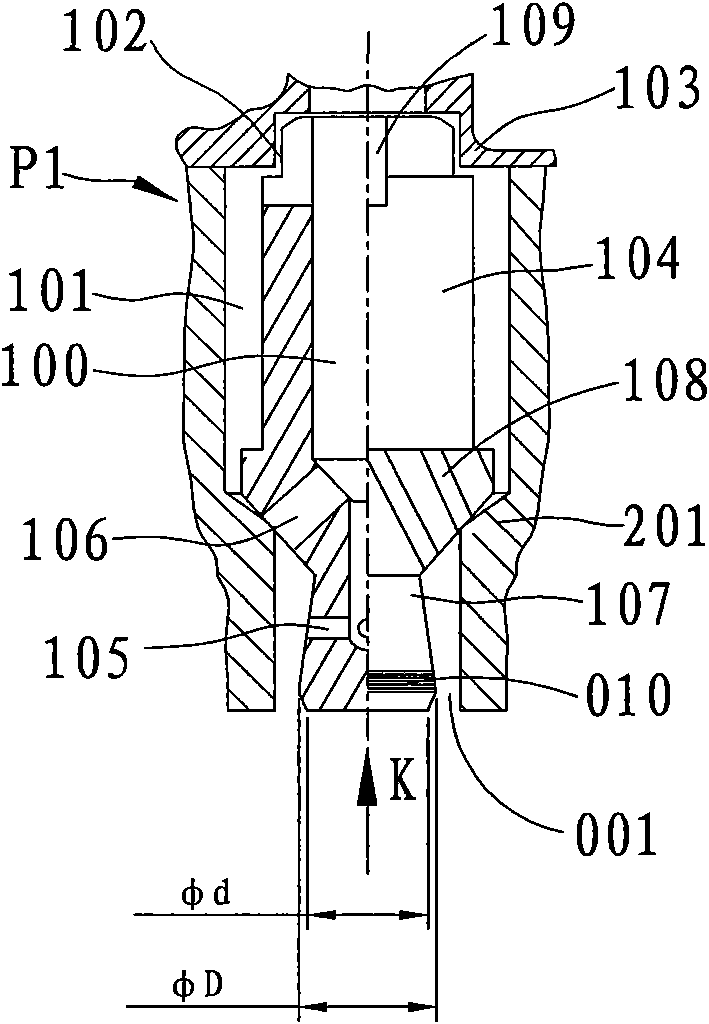
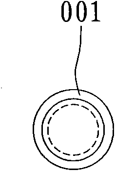
[0050] Such as Picture 1-1 As shown, a rotary annular spray nozzle p1 includes a core seat 201 , a rotary core 104 , a rotary annular spray hole 001 and a core seat cover 103 . The core seat 201 is provided with a core chamber 101, and the core seat 201 is provided with an inlet and an outlet communicating with the core chamber 101, and the inlet of the core seat 201 is connected to a pressure flow source; the two ends are small and the middle is a large stepped cylindrical rotary core 104 uses the round hole 104 of the core chamber of the core base and the round hole 102 of the core base cover 103 as bearings at both ends, and the three are concentric, and the rotating core 104 can float and rotate in the stepped circular hole core cavity 101; The head end of the big cylinder of the core is shrunk into a conical annulus and a small cylinder or a small conical column. The outer circumference of the column head 107 can be a smooth surface. The core column head 107 is located i...

Embodiment 2

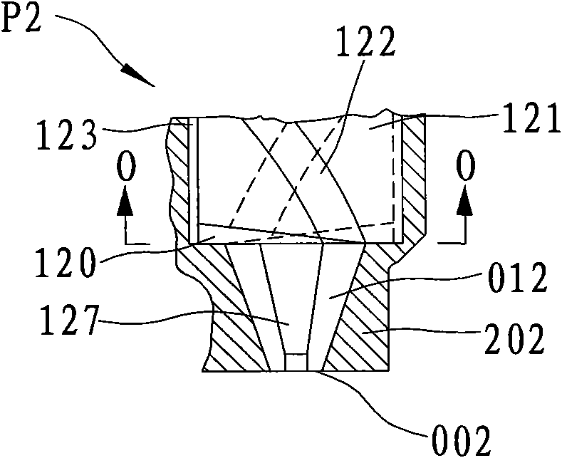
[0054] Such as Figure 1-2 As shown, a solid column rotary core spray nozzle p2. A core chamber 123 is provided in the center of the core seat 202, and a rotating core 121 that can float and rotate is provided in the round hole of the core chamber. The front end of the large cylindrical section of the rotary core 121 shrinks into a small cylindrical or small conical core column head 127. The core column head 127 is located in the inverted tapered nozzle hole at the exit of the core cavity to form an annular slot nozzle hole 012, and the inlet of the annular slot nozzle hole 012 The gap is greater than the exit gap, the outlet of the annular nozzle hole 012 is the annular nozzle 002, and the diversion groove 122 exits at the end ring surface 128 where the large cylinder and the core column head 127 are handed over (such as Figure 1-2A As shown) and communicate with the annular nozzle hole 012, the end ring surface 128 leans against the ring step of the shrinkage hole of the c...

Embodiment 3

[0056] Such as Figure 1-3 As shown, a multi-rotary core combined spray nozzle p3 with a shared core seat. It includes a seat body 135 , a core seat 203 , and rotating cores 131 , 130 , 111 . The core seat 203 is screwed on the seat body 135, and at least three outer peripheral core cavities 133, 138 and a central rotary core cavity 139 are provided on the core seat 203, and the rotatable core cavities 133, 138 are rotatably nested Stepped cylindrical rotary cores 131, 111. In this embodiment, the stepped cylindrical rotary core 131 has a stepped cylindrical shape with small two ends and an annular shoulder in the middle. The spiral tooth or the spiral groove 132, the front end of the rotary core 131 shrinks into a cylindrical core column head, and the core column head is inserted into the outlet of the rotary core cavity 133 to form an annular slot nozzle hole and its nozzle 003 whose inner annular gap is larger than the outer annular gap; Cylindrical rotary core 111 is a s...


PUM


Abstract

The invention discloses a rotary annular-seam spray nozzle comprising a core seat, a rotary core and a rotary annular-seam spray hole, wherein a core cavity is arranged in the core seat, an inlet and an outlet which are communicated with the core cavity are arranged on the core seat, a core seat inlet is communicated with a pressure flow source, the rotary core can be sleeved into the core cavity in positioning and rotating modes and is concentric with the core cavity, a rotation-promoting flow path is arranged on the rotary core or/and the wall of the core cavity in order to mutually rotate the rotary core and the core cavity by using flow power, one end of the rotary core is penetrated into the core seat outlet, and the penetrating end forms the rotary annular-seam spray hole with the inner wall of the core seat outlet. The cross section of the spray hole of the rotary annular-seam spray nozzle is an annular seam, the annular seam and a diameter can be set to respectively and conveniently control the fineness and the flow of pressure spray and make liquid drop sizes more evenly and finely distributed. The rotary annular-seam spray nozzle has a self-cleaning function, is not easy to block and is in a self-closing dust-resisting type; the rotary annular-seam spray nozzle is arranged on a spray head body or the core seat of the rotary annular-seam spray nozzle is connected with the spray head body, the spray head body is communicated with the pressure flow source, and therefore, the spray device with the rotary annular-seam spray nozzle can be formed.

Description

technical field [0001] The invention relates to a spraying device, in particular to a rotary circular seam spray nozzle capable of controlling spray fineness and the spraying device thereof, belonging to the fields of fire protection and spraying. Background technique [0002] Nozzle is the key element of spray, and the quality of spray has an important impact on the performance of water mist fire extinguishing, wet dust removal, spray drying and liquid fuel combustion. [0003] Nozzles generally have small round nozzle holes, and now some nozzles with small round holes rely on the swirling flow generated by the rotor swirl core to do atomization eruption, such as the pressure atomization small round hole nozzles given in Chinese patent 01253101.4 and 200380103103.0. Type nozzles cannot control the fineness of the spray well, and the nozzle holes are too small to be enlarged. Because when other nozzle parameters remain unchanged, the droplet size will increase rapidly with ...

Claims


Application Information

Patent Timeline
Patent Type & Authority Applications(China)
IPC IPC(8): B05B1/30B05B7/02
Inventor 韩铁夫
Owner 韩铁夫
Why Eureka
Try Eureka