Positioning method for machining workpiece and automatic clamp thereof

A positioning method and machining technology, applied in the field of machining, can solve the problems of complex shapes and the inability of stable clamping of workpieces, and achieve the effect of avoiding machining errors and stable and reliable positioning.

Active Publication Date: 2011-05-04
SHENZHEN SHANYUAN ELECTRONICS
View PDF5 Cites 16 Cited by
  • Summary
  • Abstract
  • Description
  • Claims
  • Application Information

AI Technical Summary

Problems solved by technology

[0008] In order to solve the problem in the prior art that workpieces with complex shapes and/or multi-position processing cannot be stably clamped for processing, a pos

Method used


Image

  • Positioning method for machining workpiece and automatic clamp thereof
  • Positioning method for machining workpiece and automatic clamp thereof
  • Positioning method for machining workpiece and automatic clamp thereof

Examples


Embodiment 1

[0050] A preferred embodiment of the positioning method includes the following steps:

[0051] A. Select the datum plane of the workpiece; in the designed drawings of the workpiece, it is usually the reference datum of other points, lines and surfaces. Generally speaking, a simple plane or curved surface that is not affected by the entire process can be selected as the datum plane. such as

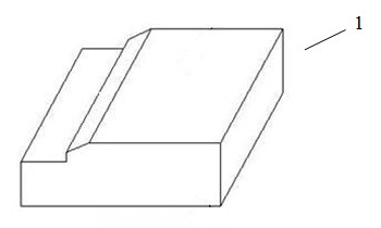
[0052] 1) When the workpiece surface is a regular surface, such as Figure 7A For the workpiece shown, the regular surface should be determined as the reference datum surface, and clamped by extension.

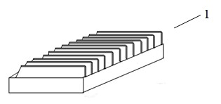
[0053] 2) When the machining surface of the workpiece is irregular and the opposite surface is regular, such as Figure 8A For the workpiece shown, the regular surface on the opposite side should be determined as the reference datum and clamped by shrinkage.

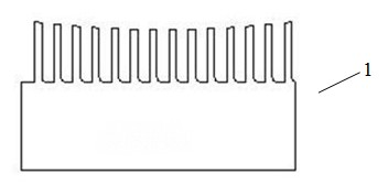
[0054] 3) When the workpiece processing surface and the opposite surface are irregular surfaces, such as Picture 9 For the workpiece shown...

Embodiment 2

[0060] As shown in FIG. 7, it is a schematic diagram of the positioning of the automatic clamp using the downward clamping method. The processing surface of the workpiece 1 to be processed and the selected reference surface are on the same side of the workpiece 1. The automatic fixture mainly includes a reference plate 31, a limiting component 33, a supporting component, and three groups of movable positioning blocks 32 and their power systems. The power system is a cylinder 41. The movable positioning block 32 is fixed on the top of the movable rod 42 of the cylinder 41 , Can move up and down with the movable rod 42. The supporting member includes a supporting seat 21 and left and right side walls 22; both ends of the side wall 22 are respectively connected to the supporting seat 21 and the reference plate 31, and an appropriate formation is formed between the side wall 22, the supporting seat 21 and the reference plate 31. Large and small space to pick and place the workpiece...

Embodiment 3

[0078] The difference between this embodiment and the second embodiment is mainly that the automatic clamp adopts a downward clamping method for positioning. As shown in FIG. 8, the processing surface of the workpiece 1 to be processed and the selected reference surface are on different sides of the workpiece 1. The workpiece 1 is placed on the support seat 21, the movable positioning block 32 is pressed down from above the workpiece 1, and the limit blocks 33 are respectively set at the appropriate positions on the front, rear, left and right sides of the reference plate 31 corresponding to the workpiece 1. . (Such as Figure 8B )

[0079] In this embodiment, because the processing surface of the workpiece 1 has a relatively large plane, the movable positioning block 32 is one, and a corresponding number of guide holes 311 are provided at the position of the movable positioning block 32 corresponding to the drilling of the workpiece 1 to further ensure the drilling The quality ...


PUM


Abstract

The invention relates to a positioning method for machining a workpiece and an automatic clamp thereof, wherein the positioning method comprises the following steps: A) selecting a reference surface of the workpiece; B) setting a reference plate, wherein the shape of the surface of the reference plate, which corresponds to the workpiece is in fit with the shape of the reference surface of the workpiece; C) setting a limiting block which is used for limiting the degree of freedom of the workpiece in the corresponding direction; and D) using a movable positioning block to push and press the workpiece to enable the workpiece to abut against the reference plate and form the surface contact. The automatic clamp mainly comprises the reference plate, a limiting part, a supporting part, the movable positioning block and a power system thereof. The automatic clamp for the positioning method can be used for positioning the workpieces in complex shapes or multi-position machining, the clamping is firm and reliable, and the problems of machining errors and the like caused by the deformation of the workpieces can be further avoided.

Description

[0001] Technical field [0002] The invention relates to the technical field of mechanical processing, in particular to a machining positioning method suitable for workpieces with regular and irregular surface shapes and multiple processing positions and an automatic clamp thereof. Background technique [0003] A common product or workpiece is a hexahedron or polyhedron structure. The processing surface and the reference surface (the so-called reference surface is a relatively fixed surface on the workpiece relative to the machine tool (or fixture) in the processing workpiece. It is used to determine other points The surface of dimensions such as, line and surface is the zero reference surface of the measurement and the starting point of other dimensions.) It does not constitute a strict vertical or flat relationship. [0004] As shown in Figure 1, the heights of the teeth formed by the tooth removal are not consistent, so the surface shape is irregular, generally like Figure 2A , 2...

Claims


Application Information

Patent Timeline
IPC IPC(8): B23Q3/00
Inventor 米春梁乃安马富勇
Owner SHENZHEN SHANYUAN ELECTRONICS
Why Eureka
Try Eureka