Three-countershaft type active transmission device of vehicle
A transmission device and intermediate shaft technology, which is applied in the field of three intermediate shaft active transmission devices for vehicles, can solve problems affecting the implementation effect of technical solutions, motor volume/power limitations, etc., and achieve compact structure, small axial space size, The effect of simple structure
- Summary
- Abstract
- Description
- Claims
- Application Information
AI Technical Summary
Problems solved by technology
Method used
Image
Examples
Embodiment 1
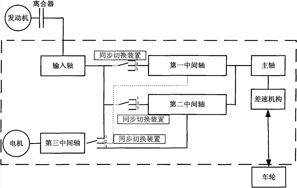
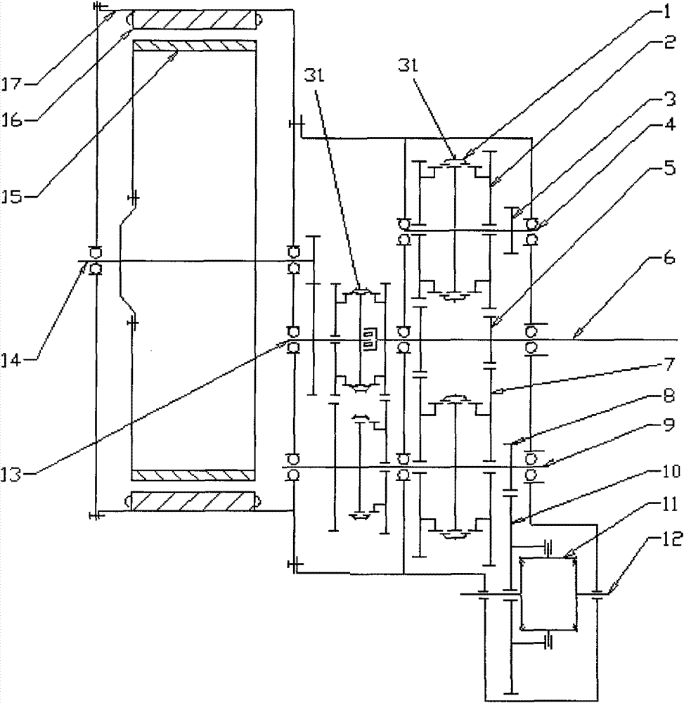
[0031] A three intermediate shaft type active transmission device for vehicles, the schematic diagram of which is as follows figure 1 As shown, the area surrounded by the dotted line is the three intermediate shaft active transmission device disclosed by the present invention, which connects the clutch and the engine through the input shaft, and connects the wheels through the output shaft. The structure of the device is as follows figure 2 As shown, it includes synchronous switching mechanism 1, transmission gear 2, final drive gear 3, second intermediate shaft 4, input gear 5, input shaft 6, transmission gear 7, final drive gear 8, first intermediate shaft 9 , final drive driven gear 10, differential 11, output shaft 12, third intermediate shaft 13, motor rotor shaft 14, motor rotor 15, motor stator 16, motor base 17, speed change manipulation mechanism 31.
[0032] In this embodiment, the first intermediate shaft 9 and the input shaft 6 are provided, and the torque from th...
Embodiment 2
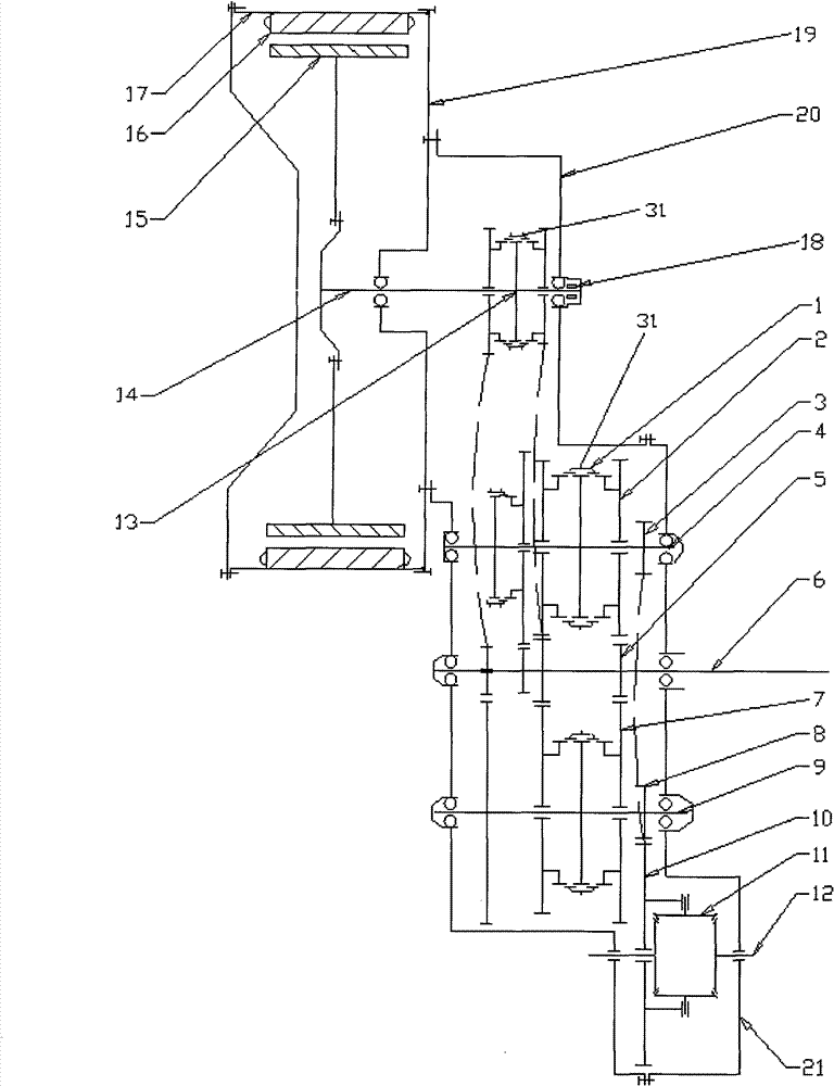
[0041] An active transmission device for a three-intermediate shaft type vehicle, its structure is as follows image 3 As shown, it includes synchronous switching mechanism 1, transmission gear 2, final drive gear 3, second intermediate shaft 4, input gear 5, input shaft 6, transmission gear 7, final drive gear 8, first intermediate shaft 9 , final drive driven gear 10, differential 11, output shaft 12, third intermediate shaft 13, motor rotor shaft 14, motor rotor 15, motor stator 16, motor base 17, motor position sensor 18, gearbox housing Body left end cover 19, gearbox housing main casing 20, gearbox housing right end cover 21, speed change control mechanism 31.
[0042] This embodiment is similar to Embodiment 1, in addition, the further improvement of this embodiment is:
[0043] 1) The motor rotor 15 is mounted on a cantilever, and is constructed as an integrated structure with the third intermediate shaft 13;
[0044] 2) The right end cover of the motor is merged wit...
PUM
 Abstract
Description
Claims
Application Information
 - R&D
- Intellectual Property
- Life Sciences
- Materials
- Tech Scout
- Unparalleled Data Quality
- Higher Quality Content
- 60% Fewer Hallucinations
Browse by: Latest US Patents, China's latest patents, Technical Efficacy Thesaurus, Application Domain, Technology Topic, Popular Technical Reports.
© 2025 PatSnap. All rights reserved.Legal|Privacy policy|Modern Slavery Act Transparency Statement|Sitemap|About US| Contact US: help@patsnap.com


