Hydraulic locking device

A locking device and hydraulic technology, which is applied in the direction of metal rolling, metal rolling racks, manufacturing tools, etc., can solve the problems that the locking degree cannot be quantitatively controlled, affects the operation of other processes, and takes up a long driving time, etc., to achieve The effects of reducing work intensity and the possibility of accidents, prolonging the service life, and improving the precision and speed of locking

Active Publication Date: 2016-03-23
TAIYUAN HEAVY IND
View PDF6 Cites 0 Cited by
  • Summary
  • Abstract
  • Description
  • Claims
  • Application Information

AI Technical Summary

Problems solved by technology

This mechanical locking method has the following defects: if the wire rope is not selected properly, there is a danger of the wire rope being broken, and the degree of locking cannot be quantitatively controlled, which can only be judged by the experience of the operator; at the same time, it takes a long time to drive when locking, which affects other process work

Method used


Image

  • Hydraulic locking device
  • Hydraulic locking device
  • Hydraulic locking device

Examples


Embodiment Construction

[0013] Example embodiments will now be described more fully with reference to the accompanying drawings. Example embodiments may, however, be embodied in many forms and should not be construed as limited to the embodiments set forth herein; rather, these embodiments are provided so that this disclosure will be thorough and complete, and will fully convey the concept of example embodiments to those skilled in the art. In the drawings, the thicknesses of regions and layers may be exaggerated for clarity. The same reference numerals in the drawings denote the same or similar structures, and thus their detailed descriptions will be omitted.

[0014] Furthermore, the described features, structures, or characteristics may be combined in any suitable manner in one or more embodiments. In the following description, numerous specific details are provided in order to give a thorough understanding of embodiments of the invention. However, one skilled in the art will appreciate that th...


PUM


Abstract

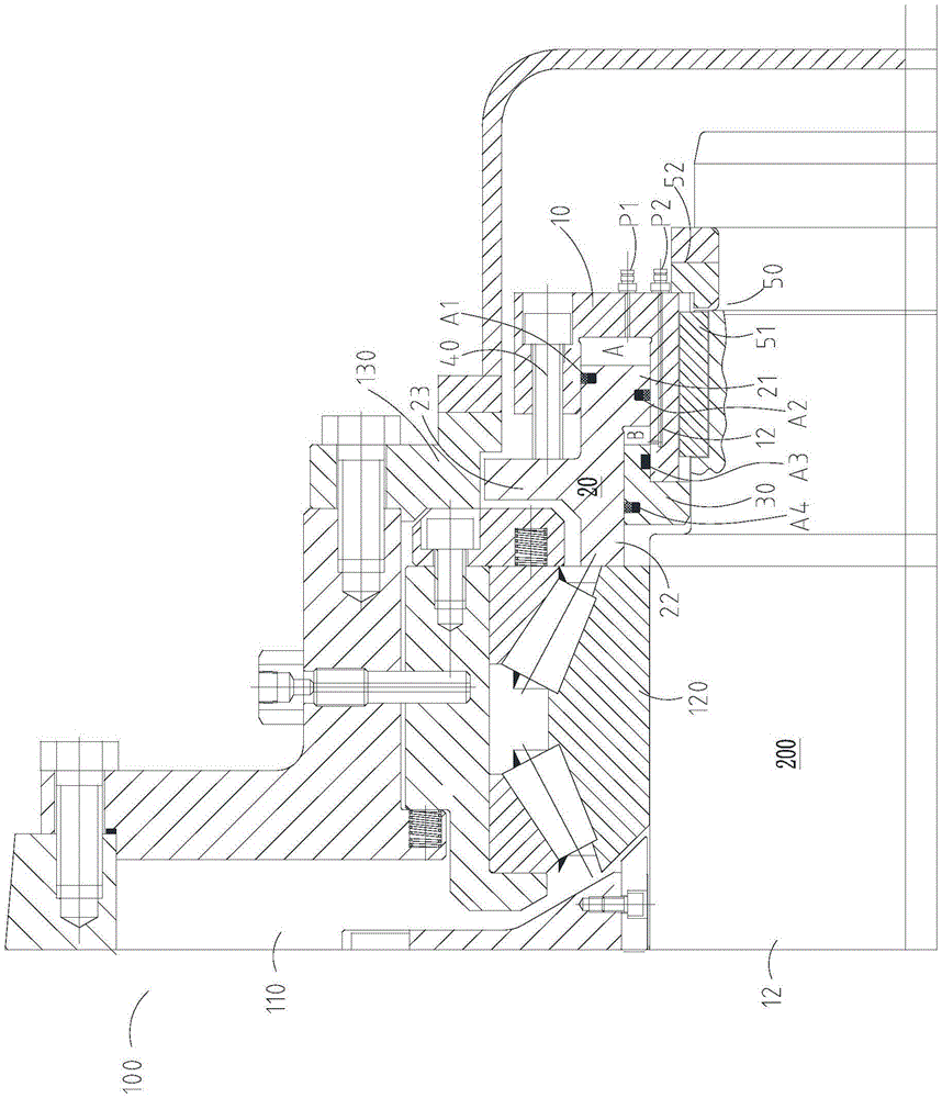
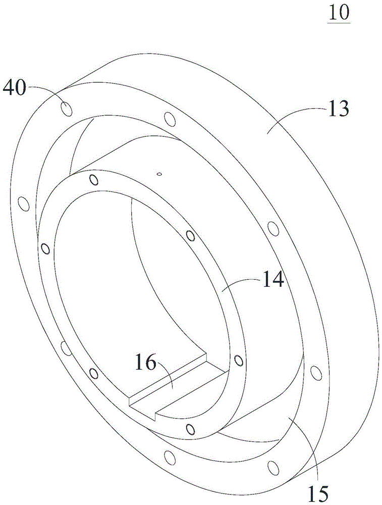
The invention provides a U-shaped oil cylinder locking device. The U-shaped oil cylinder locking device comprises an U-shaped oil cylinder, a pushing assembly, a block cover and a locking part, wherein the pushing assembly comprises an inserting part, a first pushing part and a second pushing part, the inserting part extends into the U-shaped oil cylinder and defines a first oil cavity communicated with a first oil channel with the U-shaped oil cylinder, and the pushing assembly can move in the axial direction of a roller, so that the first pushing part can push a thrust bearing and the second pushing part can push a box cover assembly; the block cover defines a second oil cavity communicated with a second oil channel with the U-shaped oil cylinder and the pushing assembly, and the locking part is connected with the U-shaped oil cylinder and can be propped against the pushing assembly; when oil is injected to the first oil cavity through the first oil channel, the pushing assembly is pushed, faces a first direction and moves in the axial direction of the roller, so that the first pushing part pushes the thrust bearing; when the oil is injected to the second oil cavity through the second oil channel, the pushing assembly is pushed, faces a second direction and moves in the axial direction of the roller, and accordingly, the second pushing part pushes the box cover assembly.

Description

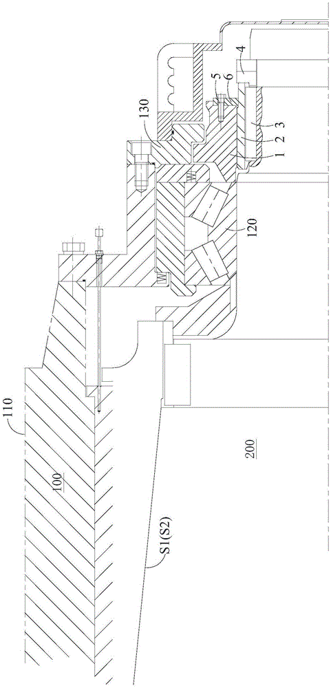
technical field [0001] The invention relates to a locking device, in particular to a hydraulic locking device for locking an oil film bearing and a roll. Background technique [0002] The oil film bearing is a key part of the rolling mill, which is composed of a radial bearing device, an axial bearing device, a locking device, a sealing device and other parts. [0003] The oil film bearing is locked to the roll by a locking device. At present, mechanical locking is one of the main locking methods for oil film bearings. [0004] Such as figure 1 The mechanical locking device shown includes a lock nut 1 , a screw ring 2 , a square key 3 , a snap ring 4 , a locking plate 5 and a screw 6 . The oil film bearing 100 includes a bearing main body 110 , a thrust bearing 120 and a case cover assembly 130 which are connected together. When locking, the spiral ring 2 is relatively fixed with the roller 200 through the square key 3 and the snap ring 4, and the steel wire rope is wound...

Claims


Application Information

Patent Timeline
Patent Type & Authority Applications(China)
IPC IPC(8): B21B31/07
CPCB21B31/07B21B31/074
Inventor 孙鹏程
Owner TAIYUAN HEAVY IND
Why Eureka
Try Eureka