Waste heat regeneration system

A waste heat recovery and heat exchanger technology, which is applied to steam engine devices, machines/engines, mechanical equipment, etc., can solve problems such as the cooling water temperature does not rise rapidly and the fuel efficiency of the engine decreases

Inactive Publication Date: 2011-05-04
TOYOTA IND CORP
View PDF5 Cites 27 Cited by
  • Summary
  • Abstract
  • Description
  • Claims
  • Application Information

AI Technical Summary

Problems solved by technology

Therefore, the temperature of the cooling water does not rise rapidly, and the fuel efficiency of the engine decreases

Method used


Image

  • Waste heat regeneration system
  • Waste heat regeneration system
  • Waste heat regeneration system

Examples


Embodiment Construction

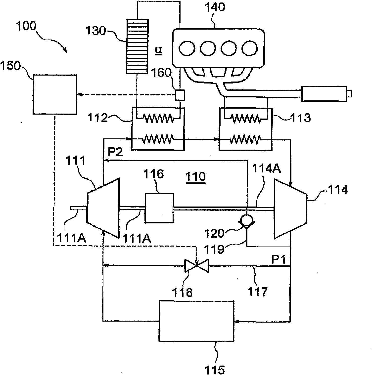
[0017] Embodiments of the present invention will be described below with reference to the accompanying drawings. figure 1 A waste heat recovery system 100 according to a first embodiment of the present invention is shown. The waste heat recovery system 100 includes a Rankine cycle 110 . The Rankine cycle 110 has a gear pump 111 , a cooling water boiler 112 , an exhaust boiler 113 , an expander 114 , and a condenser 115 . The gear pump 111 is provided for pumping working fluid. The cooling water boiler 112 is provided for exchanging heat between the working fluid and the cooling water exchanging heat with the engine 140, which serves as the first heat exchanger of the present invention. The exhaust gas boiler 113 is provided for heat exchange between the working fluid and the exhaust gas of the engine 140, which serves as the second heat exchanger of the present invention. The expander 114 is configured to expand the working fluid heated and vaporized by the cooling water bo...


PUM


Abstract

The waste heat recovery system of an engine includes a Rankine cycle, a first bypass passage, a first valve and a control unit. The Rankine cycle allows a working fluid to circulate therethrough. The Rankine cycle has a first heat exchanger, a second heat exchanger, an expander and a condenser. The first heat exchanger exchange heat between the working fluid and the engine or a first intermediatemedium exchanging heat with the engine. The first bypass passage allows the working fluid to pass therethrough. One end of the first bypass passage is located at an upstream side of the condenser andthe other end is located at a downstream side of the condenser. The first valve opens and closes the first bypass passage. When temperature of the engine or the first intermediate medium is lower than a first predetermined value, the control unit opens the first valve.

Description

technical field [0001] The present invention relates to a waste heat recovery system, and more particularly, to a waste heat recovery system using a Rankine cycle. Background technique [0002] Waste heat recovery systems using the Rankine cycle have been developed to recover mechanical energy (power) from waste heat of vehicle engines. The Rankine cycle generally includes a pump that pumps a working fluid, a heat exchanger that heats the working fluid by waste heat from an engine, an expander that expands the heated working fluid to recover mechanical energy, and a condenser that condenses the expanded working fluid. [0003] Japanese Patent Application Publication No. 2007-85195 discloses a waste heat recovery system having two heat exchangers. The Rankine cycle of the waste heat recovery system includes a first heat exchanger and a second heat exchanger. The first heat exchanger heats the working fluid by exchanging heat with the cooling water of the engine. Gas heat ex...

Claims


Application Information

Patent Timeline
Patent Type & Authority Applications(China)
IPC IPC(8): F02G5/02F01K11/00
CPCF01K23/065F01K13/02
Inventor 森英文井口雅夫榎岛史修川口真广
Owner TOYOTA IND CORP
Why Eureka
Try Eureka