Heatpump type gas-fired boiler waste heat recovery unit

A gas-fired boiler and waste heat recovery technology, applied in the field of energy technology applications, can solve the problems of inability to realize the recovery of flue gas condensation heat, insufficient utilization of sensible heat and latent heat, etc.

Active Publication Date: 2010-06-09
TSINGHUA UNIV +1
View PDF0 Cites 27 Cited by
  • Summary
  • Abstract
  • Description
  • Claims
  • Application Information

AI Technical Summary

Problems solved by technology

[0002] At present, the exhaust gas temperature of gas-fired boilers is above 100°C. This part of the flue gas not only takes away most of the sensible heat, but also does not fully utilize its latent heat. This is because the exhaust gas temperature

Method used


Image

  • Heatpump type gas-fired boiler waste heat recovery unit
  • Heatpump type gas-fired boiler waste heat recovery unit
  • Heatpump type gas-fired boiler waste heat recovery unit

Examples


Embodiment 1

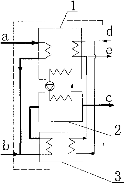
[0014] Embodiment 1: see attached figure 1 , in actual operation, natural gas first enters the absorption heat pump unit 1 as a driving heat source, releases heat in its generator, and discharges from the absorption heat pump 1 when the temperature drops to about 130°C, and enters the flue gas together with the exhaust gas of the gas boiler- The water heat exchanger 3 is used as a heating source, and after cooling down to 70°C, it is discharged from the air-water heat exchanger, and the flue gas at 70°C enters the flue gas condensation heat exchanger 2 and is cooled to 30°C before being discharged; the secondary side is 45°C The hot water return water enters the unit in two ways, one way enters the absorption heat pump 1, absorbs heat in its absorber and condenser, and flows out after being heated to about 60°C, and the other way enters the flue gas-water heat exchanger 3, and The flue gas on the primary side undergoes heat exchange, is heated to 60°C and then flows out, and t...

Embodiment 2

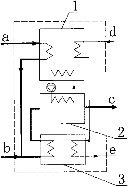
[0015] Embodiment 2: see attached figure 2 , Natural gas first enters the absorption heat pump unit 1 as a driving heat source, releases heat in its generator, and is discharged from the absorption heat pump 1 when the temperature drops to about 130°C, and enters the flue gas-water heat exchanger together with the exhaust gas of the gas-fired boiler 3 As a heating source, after cooling down to 70°C, it is discharged from the air-water heat exchanger, and the flue gas at 70°C enters the flue gas condensation heat exchanger 2 and then discharged after cooling down to 30°C; the hot water at 45°C on the secondary side returns to The water enters the absorption heat pump 1, absorbs heat in its absorber and condenser, is heated and then enters the air-water heat exchanger 2, exchanges heat with the primary side flue gas, and is heated to 60°C before being sent to the user.

Embodiment 3

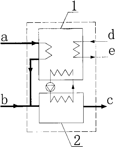
[0016] Embodiment 3: see attached image 3 , in actual operation, natural gas first enters the absorption heat pump unit 1 as the driving heat source, releases heat in its generator, and the flue gas is discharged from the absorption heat pump 1, and enters the flue gas condensation heat exchange together with the 90°C exhaust gas of the gas-fired boiler The heat pump 2 cools down to 30°C and then discharges; the hot water return water at 45°C on the secondary side enters the absorption heat pump 1, is heated to 60°C and then sent to the user.


PUM


Abstract

The invention belongs to the field of energy technology application, particularly relates to a heatpump type gas-fired boiler waste heat recovery unit. The unit comprises an absorption heat pump, a flue gas-water heat exchanger, a flue gas condensation heat exchanger, various connecting pipelines and accessories. The connecting pipelines comprise a first side pipeline, a middle water circulating pipeline and a second side pipeline. First side natural gas as a driving heat source enters a generator of the absorption heat pump and then enters the flue gas-water heat exchanger and the flue gas condensation heat exchanger with smoke exhausted by the gas fired boiler, the natural gas firstly passes through a water side circulating pipeline of the flue gas-water heat exchanger to heat second side return hot water and then exchanges heat with the generator side of the absorption heat pump to be as a low level heat source through the middle water circulating pipeline of the flue gas condensation pipeline, and the heat is transferred to a second side heating network by the absorption heat pump. The unit realizes cascade utilization for flue gas heat, greatly reduces the temperature of exhausted smoke, improves the energy utilization efficiency and is mainly used for gas-fired boiler waste heat recovery in a heating system.

Description

technical field [0001] The invention belongs to the application field of energy technology, and in particular relates to a heat pump type gas boiler waste heat recovery unit capable of greatly reducing exhaust gas temperature. Background technique [0002] At present, the exhaust gas temperature of gas-fired boilers is above 100°C. This part of the flue gas not only takes away most of the sensible heat, but also does not fully utilize its latent heat. This is because the exhaust gas temperature is determined by the thermal requirements of the user. Therefore, how to further reduce the exhaust gas temperature, realize the cascade utilization of energy, and realize the effect of energy saving and emission reduction is of great significance. Contents of the invention [0003] In order to solve the deficiencies in the prior art, the present invention particularly provides a heat pump type gas boiler waste heat recovery unit capable of greatly reducing exhaust gas temperature. ...

Claims


Application Information

Patent Timeline
IPC IPC(8): F24H8/00F25B27/02
CPCY02B30/123Y02B30/52Y02B30/102Y02A30/274Y02B30/00Y02P80/15
Inventor 赵玺灵付林张世钢李岩江亿
Owner TSINGHUA UNIV
Why Eureka
Try Eureka