Synergic-purification all-heat-recovery combined heat and power generation system

A technology of combined heat and power generation and total heat recovery, applied in the energy field, can solve problems such as poor heat exchange effect, large volume, and waste of heat

Inactive Publication Date: 2016-05-25
TSINGHUA UNIV
View PDF6 Cites 16 Cited by
  • Summary
  • Abstract
  • Description
  • Claims
  • Application Information

AI Technical Summary

Problems solved by technology

In recent years, gas-steam combined cycle heat and power cogeneration technology has been greatly developed, but there is still a lot of room for improvement in the efficiency of heat sources. At the same time, environmental protection pressure has also put forward higher requirements for the purification of system exhaust
To improve efficiency, it is necessary to consider the use of the latent heat in the flue gas and the condensation heat discharged from the steam turbine. Because the return water temperature of the urban heating network is high, it is difficult to provide low-temperature refrigerant to recover the two kinds of waste heat when returning to the thermal power plant, resulting in huge losses. waste of heat
[0003] Aiming at this problem, the existing technology proposes a new type of energy supply system based on gas-steam combined cycle heat and power cogeneration. In the thermal power plant, the mode of integrating the partition flue gas heat exchanger and the heat pump is designed to recover the waste steam waste heat and flue gas. The gas waste heat process can recover part of the waste heat, but there are still two problems to be solved in this system. One is that the return water temperature of the heating network is still high, and the waste heat of flue gas and exhaust

Method used


Image

  • Synergic-purification all-heat-recovery combined heat and power generation system
  • Synergic-purification all-heat-recovery combined heat and power generation system
  • Synergic-purification all-heat-recovery combined heat and power generation system

Examples


Embodiment 1

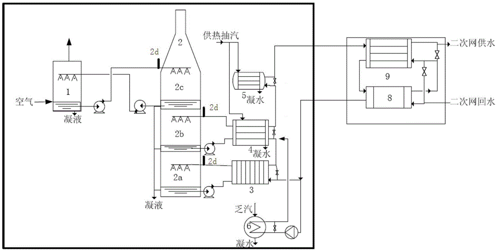
[0042] Such as figure 1 As shown, the air enters the air humidification device 1 and then enters the original cogeneration system after being humidified. The condensate at the bottom of the air humidification device 1 is pumped into the third gas water heating tower 2c for spraying through the water pump, and the condensate is pumped into the third air water heating tower 2c after spraying. In the air humidifier 1, the humidification function of air is realized. The spray water at the bottom of the second gas-water heating tower 2b is pumped into the spray water side of the absorption heat pump 4 through the water pump to release heat to the water side of the heating network, and then returns to the top of the second gas-water heating tower 2b for circulating spraying. The spray water at the bottom of the first gas-water heating tower 2a is pumped into the water-water heat exchanger 3 to spray the water side to release the heat to the water side of the heating network, and the...

Embodiment 2

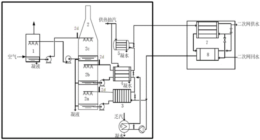
[0046] Such as figure 2 As shown, the difference between this embodiment and Embodiment 1 is that when the secondary side of the thermal station is in the low-temperature heating mode, the thermal station only includes the conventional second water-to-water heat exchanger 9, and the second water-to-water heat exchanger The primary side inlet of 9 is connected to the water side outlet of steam-water heat exchanger 5, and the primary side low-temperature return water interface of the second water-water heat exchanger 9 is connected to the water side inlet of condenser 6 and water-water heat exchanger 3 Connection; the secondary network return water of the thermal station is connected to the secondary side low-temperature return water interface of the second water-to-water heat exchanger 9, and the secondary network water supply of the thermal station is connected to the secondary-side water supply of the second water-to-water heat exchanger 9 The interface is connected, and aft...

Embodiment 3

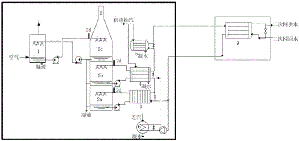
[0048] Such as image 3 As shown, the difference between this embodiment and Embodiment 1 is: when the secondary side of the thermal station is in the low-temperature heating mode, the thermal station includes a conventional second water-to-water heat exchanger 9 and a peak-shaving heat pump unit 8; The primary-side inlet of the second water-water heat exchanger 9 is connected to the water-side outlet of the steam-water heat exchanger 5, and the primary-side low-temperature return water interface of the second water-water heat exchanger 9 is connected to the primary side of the peak-shaving heat pump unit 8. Inlet connection, the outlet of the primary side of the peak-shaving type heat pump unit 8 is connected to the water side inlet of the condenser 6 and the water-water heat exchanger 3; The secondary side low-temperature return water interface is connected to the secondary side low-temperature return water interface of the peak-shaving heat pump unit 8; The secondary-side ...


PUM


Abstract

The invention relates to a synergic-purification all-heat-recovery combined heat and power generation system which comprises a heat power plant waste heat utilization system and a heating station, wherein the heat power plant waste heat utilization system is connected with the heating station through a heat supply network return water supply pipeline; and the heat power plant waste heat utilization system comprises an air humidifier, a gas-water thermal tower, a water-to-water heat exchanger, an absorption heat pump, a steam-to-water heat exchanger and a steam condenser. In the heat power plant, the air is humidified to enhance the dew-point temperature of flue gas; the return water temperature is further lowered in the heating station, so that the heat supply network return water is lowered to 10 DEG C and even lower; and the two measures are integrated to recover all the flue gas waste heat and dead steam waste head. Meanwhile, a dosing port is arranged on a flue gas waste heat recovery spray water path, so that the flue gas is cleaned in the waste heat recovery process, thereby achieving favorable denitrification effects. The acidic condensation water is neutralized to achieve the discharge standard, thereby integrating the functions of waste heat recovery and flue gas purification. The synergic-purification all-heat-recovery combined heat and power generation system is suitable for combustible gas heat power plants, biomass heat power plants and the like, and can be further popularized to coal-burning heat power plants and boilers.

Description

technical field [0001] The invention relates to a cogeneration system of cogeneration of heat and power with synergistic purification and total heat recovery, which belongs to the field of energy technology. Background technique [0002] For district heating, a typical way of using natural gas is gas-steam combined cycle heat and power cogeneration for heating. In recent years, the gas-steam combined cycle heat and power cogeneration technology has been greatly developed, but there is still a lot of room for improvement in the efficiency of the heat source. At the same time, the pressure of environmental protection has also put forward higher requirements for the purification of system exhaust. To improve efficiency, it is necessary to consider the use of the latent heat in the flue gas and the condensation heat discharged from the steam turbine. Because the return water temperature of the urban heating network is high, it is difficult to provide low-temperature refrigerant ...

Claims


Application Information

Patent Timeline
IPC IPC(8): F24D3/18F23L7/00F23J15/04F23J15/06B01D53/78B01D53/56
CPCB01D53/56B01D53/78B01D2257/404F23J15/04F23J15/06F23J2215/10F23L7/002F23L2900/07008F24D3/18F24D2200/18F24D2200/32Y02E20/30Y02P80/15
Inventor 赵玺灵付林张世钢魏茂林王静贻
Owner TSINGHUA UNIV
Why Eureka
Try Eureka