Locomotive fault diagnosis method and system

A fault diagnosis system and fault diagnosis technology, applied in the direction of railway vehicle testing, etc., can solve problems such as failure to form, lack of fault guidance ability, vague definition of locomotive faults, etc., and achieve the effect of complete functions

Inactive Publication Date: 2011-05-04
DATONG ELECTRIC LOCOMOTIVE OF NCR
View PDF0 Cites 83 Cited by
  • Summary
  • Abstract
  • Description
  • Claims
  • Application Information

AI Technical Summary

Problems solved by technology

[0003] With the continuous advancement of technology, the railway equipment has also been continuously upgraded. Microcomputer network control systems have been widely used on locomotives, and their powerful functions have been recognized by people. Some units have already possessed preliminary fault diagnosis capabilities. The definiti

Method used


Image

  • Locomotive fault diagnosis method and system
  • Locomotive fault diagnosis method and system
  • Locomotive fault diagnosis method and system

Examples


Embodiment 1

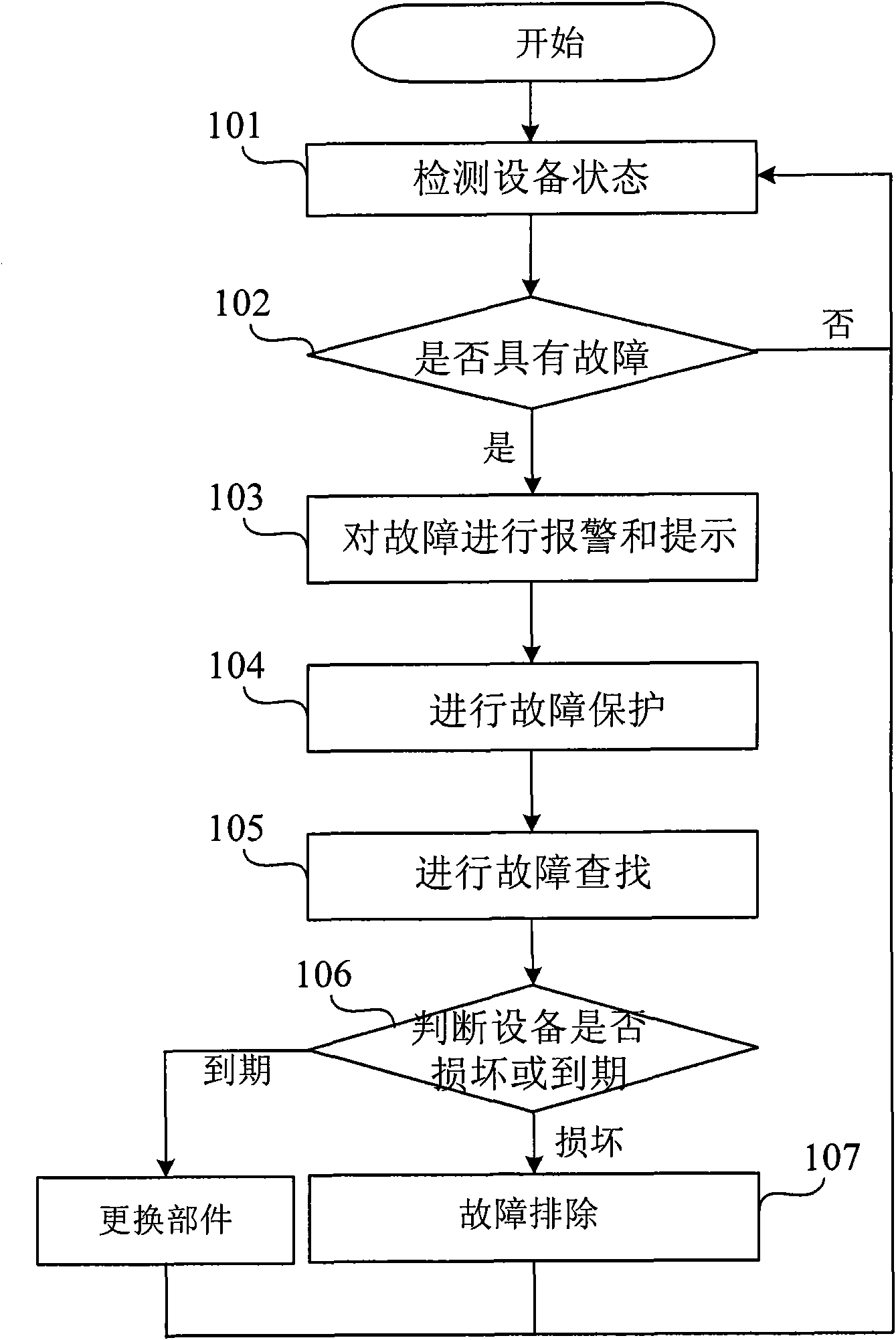
[0049] Figure 4 This is a flowchart of Embodiment 1 of the method for diagnosing a locomotive fault in the present invention. As shown in the figure, Embodiment 1 of the method for diagnosing a locomotive fault of the present invention specifically includes the following steps:

[0050] Step 201: Obtain monitoring data collected when the sampling device monitors the locomotive equipment;

[0051] That is, the sampling device in the above-mentioned locomotive fault diagnosis system performs signal detection on the locomotive equipment, and obtains the status signal;

[0052] Step 202: Compare the monitored data with the variable status or the fault data threshold in the fault information of the locomotive equipment in the database. If the variable status of the monitored data is abnormal or the value exceeds the fault data threshold, call the fault of the locomotive equipment from the database. Information failure prompt information and display, save the locomotive equipment failure ...

Embodiment 2

[0063] Image 6 This is a flowchart of the second embodiment of the locomotive fault diagnosis method of the present invention. As shown in the figure, the second embodiment of the locomotive fault diagnosis method of the present invention specifically includes the following steps:

[0064] Step 401: Establish the hardware and software foundation of the locomotive fault diagnosis method;

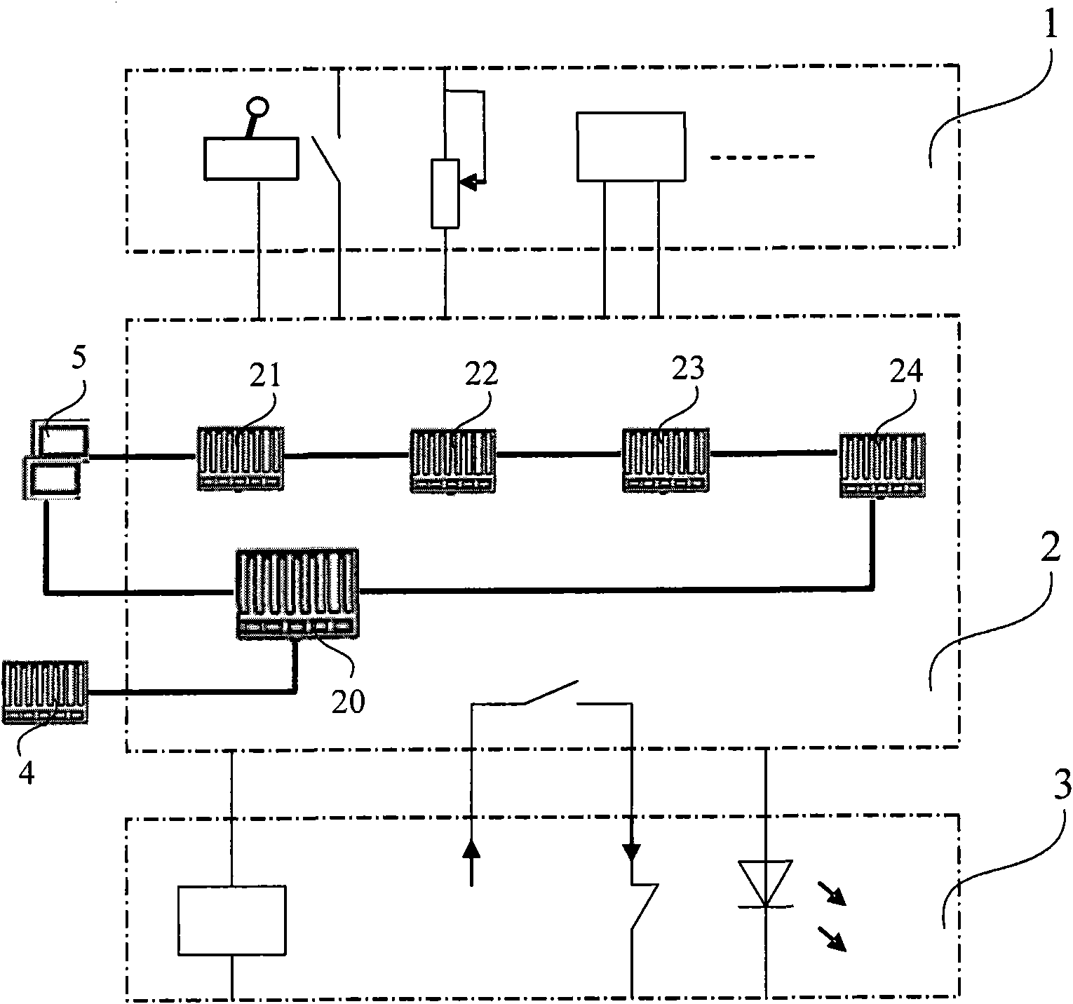
[0065] The hardware system should include figure 1 The equipment included in the system, and should try to consider the compatibility of the fault diagnosis system hardware with the locomotive computer network control system. In order to make the fault diagnosis system reasonable and clear, and to facilitate fault judgment and analysis, it is necessary to name and define faults accurately and reasonably, reasonably confirm the fault code and fault name in the fault information, and define the fault level according to the impact of the fault on the operation of the locomotive; Define the fault pr...


PUM


Abstract

The invention discloses a locomotive fault diagnosis method and system. The method comprises the following steps: obtaining monitored data acquired when a sampling device monitors locomotive equipment; comparing the monitored data with an equipment variable state or a data threshold in the fault information of the locomotive equipment in a database; if the variable state of the monitored data is abnormal or a sampling value exceeds a fault data threshold, calling fault prompting information of the fault information of the locomotive equipment from the database and displaying the fault prompting information; storing the fault information and monitored data of the locomotive equipment in storage equipment of a locomotive control unit; and carrying out fault handling on the locomotive equipment according to the fault prompting information of the locomotive equipment. Therefore, by utilizing the locomotive fault diagnosis method and system provided by the invention, all equipment of the whole locomotive can be monitored, the fault handling is carried out on the locomotive equipment with faults, and the fault information is stored, therefore, a set of complete locomotive fault diagnosis method and system is established, so that the function for locomotive fault diagnosis is more perfected.

Description

Technical field [0001] The invention relates to a method and system for diagnosing locomotive faults, in particular to a method and system for monitoring and diagnosing locomotive faults. Background technique [0002] Due to the long running time of the locomotive online, the harsh working environment, and the high operating density, once a failure occurs, it will affect the operation of the entire railway line. Therefore, the reliability, availability, maintainability and safety (RAMS) of the locomotive operation are judgments An important criterion for the quality of locomotives. Railway operation safety has always been a very important issue. In order to improve the reliability and safety of locomotives, corresponding diagnostic equipment has been developed for a certain function or system of locomotives, but these equipment are independent of each other and often collect and process signals separately. , And then pass the result to the control system or access the protection...

Claims


Application Information

Patent Timeline
IPC IPC(8): G01M17/08
Inventor 谢曲波仝雷高健
Owner DATONG ELECTRIC LOCOMOTIVE OF NCR
Why Eureka
Try Eureka