Automatic charging system and method

An automatic charging and charging stand technology, applied in electromagnetic wave systems, current collectors, electric vehicles, etc., can solve the problems of time-consuming, unable to find a charging stand, etc., and achieve the effect of fast return speed and strong electromagnetic signal penetration.

Inactive Publication Date: 2011-05-04
HONG FU JIN PRECISION IND (SHENZHEN) CO LTD +1
View PDF0 Cites 16 Cited by
  • Summary
  • Abstract
  • Description
  • Claims
  • Application Information

AI Technical Summary

Problems solved by technology

However, the use of infrared transceivers to guide and move movable devices is limited by the straight-line propagation of infrared light
If you encounter obstacles in

Method used


Image

  • Automatic charging system and method
  • Automatic charging system and method
  • Automatic charging system and method

Examples


Embodiment Construction

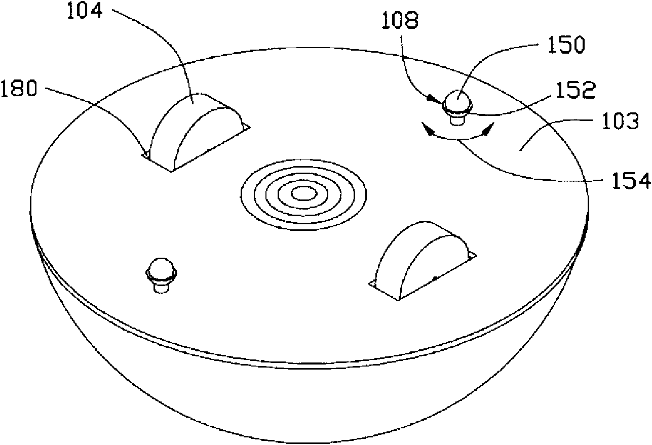
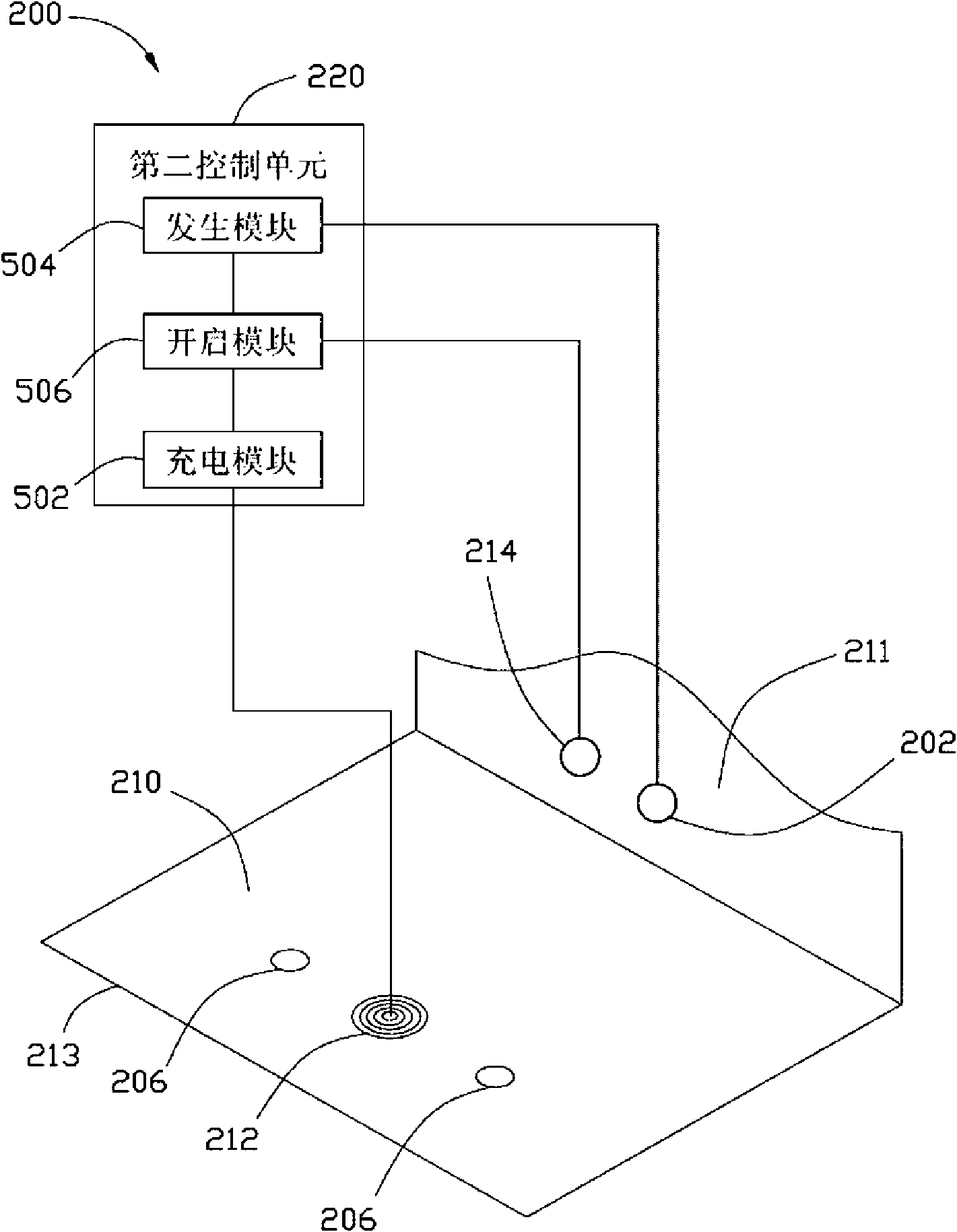
[0020] Please also refer to Figure 1 to Figure 3 , the automatic charging system according to the preferred embodiment of the present invention includes a movable device 100 and a charging stand 200 . The movable device 100 includes a body 101, a rechargeable battery (not shown), two actuating wheels 104, two auxiliary wheels 108, two magnetic switches 106, a first charging device 112, an electromagnetic sensor 102 and a The first control unit 109 .

[0021] Please also refer to Figure 1 to Figure 2 , the body 101 includes a circular bottom plate 103 and a hemispherical upper cover 105 . The upper cover 105 is disposed on the bottom plate 103 to form a receiving space (not shown). The bottom plate 103 defines two square through holes 180 and two cuboid covers 182 . The through holes 180 are arranged symmetrically along the left and right sides of the bottom plate 103 . The cover body 182 has a cuboid cavity 110 . Each cover 182 covers the corresponding through hole 180...


PUM


Abstract

The invention provides an automatic charging system, which comprises a movable device and a charging seat. The movable device comprises an electromagnetic sensor, two magnetic switches and a first charging device arranged in the middle of the two magnetic switches; and the charging seat comprises a generating device, two magnetic pieces corresponding to the two magnetic switches, and a second charging device arranged in the middle of the two magnetic pieces, wherein the generating device transmits a first electromagnetic signal to construct a communication range; the electromagnetic sensor is used for receiving the first electromagnetic signal in the communication range so as to guide the movable device to move to the charging seat; and after the two magnetic switches sense the two magnetic pieces, the second charging device charges the first charging device in a wireless charging mode or an electrode contact mode. Because the electromagnetic signal has high penetrating power and is easily received by the electromagnetic sensor, the movable device has high return speed. The invention also provides an automatic charging method.

Description

technical field [0001] The invention relates to automatic electronic technology, in particular to an automatic charging system and method. Background technique [0002] At present, automated electronic devices (hereinafter referred to as movable devices), such as automatic vacuum cleaners, are widely used in various fields. In order to make the movable device have a higher degree of freedom of movement, it usually uses a rechargeable battery as a power source to avoid being bound by cables. At present, the movable device generally includes a plurality of infrared transceivers and controllers, and the charging base for charging the rechargeable battery of the movable device is also equipped with infrared transceivers. When the power of the rechargeable battery of the movable device is about to run out, the movable device will be controlled by the controller to move to look for the charging base. Specifically, the movable device receives the infrared signal sent by the infra...

Claims


Application Information

Patent Timeline
IPC IPC(8): H02J7/00H02J17/00
Inventor 聂剑扬
Owner HONG FU JIN PRECISION IND (SHENZHEN) CO LTD
Why Eureka
Try Eureka