Revolving opening door air-powered goal on door panel of bowling equipment

A door-opening and equipment technology, applied in bowling balls, sports accessories, etc., can solve the problems of not being able to roll out of the ball door in time, inconvenient installation, adjustment, maintenance, and impact on bottle operation, etc., to achieve convenient transformation, strong integrity, Run Reliable Effects

Inactive Publication Date: 2008-07-30
何帮喜
View PDF1 Cites 3 Cited by
  • Summary
  • Abstract
  • Description
  • Claims
  • Application Information

AI Technical Summary

Problems solved by technology

One is that the ball can only roll out of the goal when the goal board is underspinned in place, otherwise there will be a "threshold" at the goal, so that the ball cannot be rolled out of the goal in time and quickly, and the goal board needs to be reliably and in place after all. For a certain period of time, the diameter of the ball is generally evenly smaller than the diameter of the goal door, so the downward rotation of the goal board has an insurmountable technical problem for the timely and fast return of the ball; A concave arc that forms a gap between the edge line of the goal and the edge of the goal", this is the need for the light control signal path, but, as can be seen from the figure, there must be a convex arc on the goal board opposite to the concave arc , so that when the goal board is in the closed position, another gap is formed between the edge line of the goal door, that is, the goal board is also cut off by a convex arc, otherwise the goal board cannot be in place when it spins down, and the ball cannot go out The gate, because there is an overall height requirement for the installation of the fairway, which determines the height of the gate, and a piece of the goal board must be cut to

Method used


Image

  • Revolving opening door air-powered goal on door panel of bowling equipment
  • Revolving opening door air-powered goal on door panel of bowling equipment

Examples


Embodiment Construction

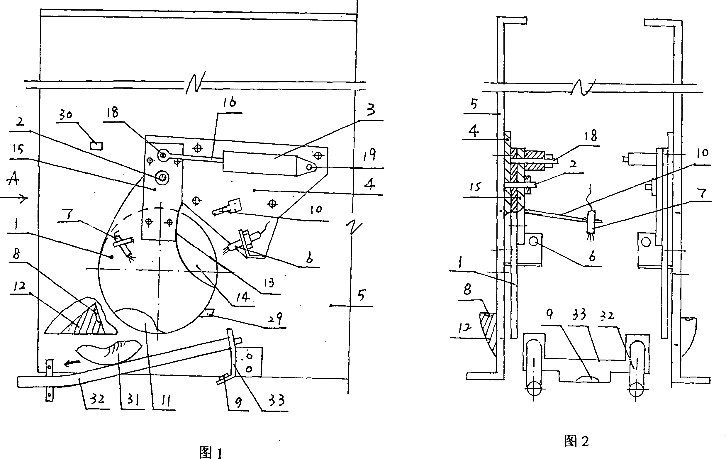
[0013] Further detailed description in conjunction with the accompanying drawings: 31-shown as a ball, the arrow shows the direction of motion of the ball 31.

[0014] As shown in Figures 1, 2, and 3, the light control switch control mechanism is a mirror reflection type, and the photoelectric head is a matching door-opening photoelectric head 6 and door-closing photoelectric head 7 are installed separately, and the door-opening photoelectric head 6 provides the door opening signal of the goal board 1 , the door-closing photoelectric head 7 provides the door-closing signal of the goal board 1, the door-opening photoelectric head 6 is installed on the assembly frame 4, and its matching door-opening reflector 8 is installed on the guard plate 12 inside the goal door 11, and the door-closing photoelectric head 7 is installed On the pole 10 that is fixed on the assembly plate frame 4, or be contained in in addition on the support of the ball return acceleration device, its matching...


PUM


Abstract

The invention relates to an open-door pneumatic goal with a spinning up door plate in bowling equipment, which pertains to the sports equipment field and mainly solves the problems of the open-door pneumatic goal with the spinning up door plate and integrity; the invention is provided with a goal door plate (1), corresponding horizontal rotary shaft (2), a cylinder (3) that drives the goal door plate (1) to open and close in a vertical rotation way, a control mechanism of a light control switch and air control and electronic control systems; each part is arranged on an assembling frame plate (4); the goal door plate (1) is a spinning up open-door structure, which is arranged at the outer side face of a wallboard (5) and is globally adjustable and dismountable; the control mechanism of the light control switch is mirror reflection type; a matching open-door photoelectric head (6) and a close-door photoelectric head (7) are arranged in a discrete way; the invention can further promote ball returning speed and has strong integrity, convenient manufacturing, installation, adjustment, maintenance or whole replacement and reliable operation; two adjacent lanes are easily interlocked, which is especially convenient for improving the goal of old lanes and extremely easy to carry out coordinative adjustment with a ball return accelerating device.

Description

technical field [0001] The invention belongs to the field of sports equipment and relates to a swing-opening type pneumatic goal on a door plate in bowling equipment. Background technique [0002] In the prior art, the disclosed application number of publication number CN1751764A is 200510086431·5 "pneumatic goal in bowling equipment". Moreover, the structure is simple and the operation is reliable, but there are still deficiencies. One is that the ball can only roll out of the goal when the goal board is underspinned in place, otherwise there will be a "threshold" at the goal, so that the ball cannot be rolled out of the goal in time and quickly, and the goal board needs to be reliably and in place after all. For a certain period of time, the diameter of the ball is generally evenly smaller than the diameter of the goal door, so the downward rotation of the goal board has an insurmountable technical problem for the timely and fast return of the ball; A concave arc that fo...

Claims


Application Information

Patent Timeline
IPC IPC(8): A63D5/02
Inventor 何帮喜
Owner 何帮喜
Why Eureka
Try Eureka