Digital phase lock amplifier

A digital phase-locking and amplifier technology, applied in the field of weak signal detection and amplification equipment, can solve the problems of signal conversion error phase accuracy, unsatisfactory use effect, low low-pass cut-off frequency, etc., to achieve frequency nonlinearity elimination, absolute value accuracy, Effect of Low Cutoff Frequency

Inactive Publication Date: 2011-05-04
SUN YAT SEN UNIV
View PDF3 Cites 35 Cited by
  • Summary
  • Abstract
  • Description
  • Claims
  • Application Information

AI Technical Summary

Problems solved by technology

The digital lock-in amplifier uses an average value filter to achieve phase-sensitive correlation detection, but the low-pass cut-off frequency of the average filter is low, the attenuation slope is large, and the required order is more than that of the IIR filter, and the effect is not ideal.
In addition, the squ

Method used


Image

  • Digital phase lock amplifier
  • Digital phase lock amplifier
  • Digital phase lock amplifier

Examples


Embodiment Construction

[0030] The present invention will be described in more detail below in conjunction with the accompanying drawings and specific embodiments.

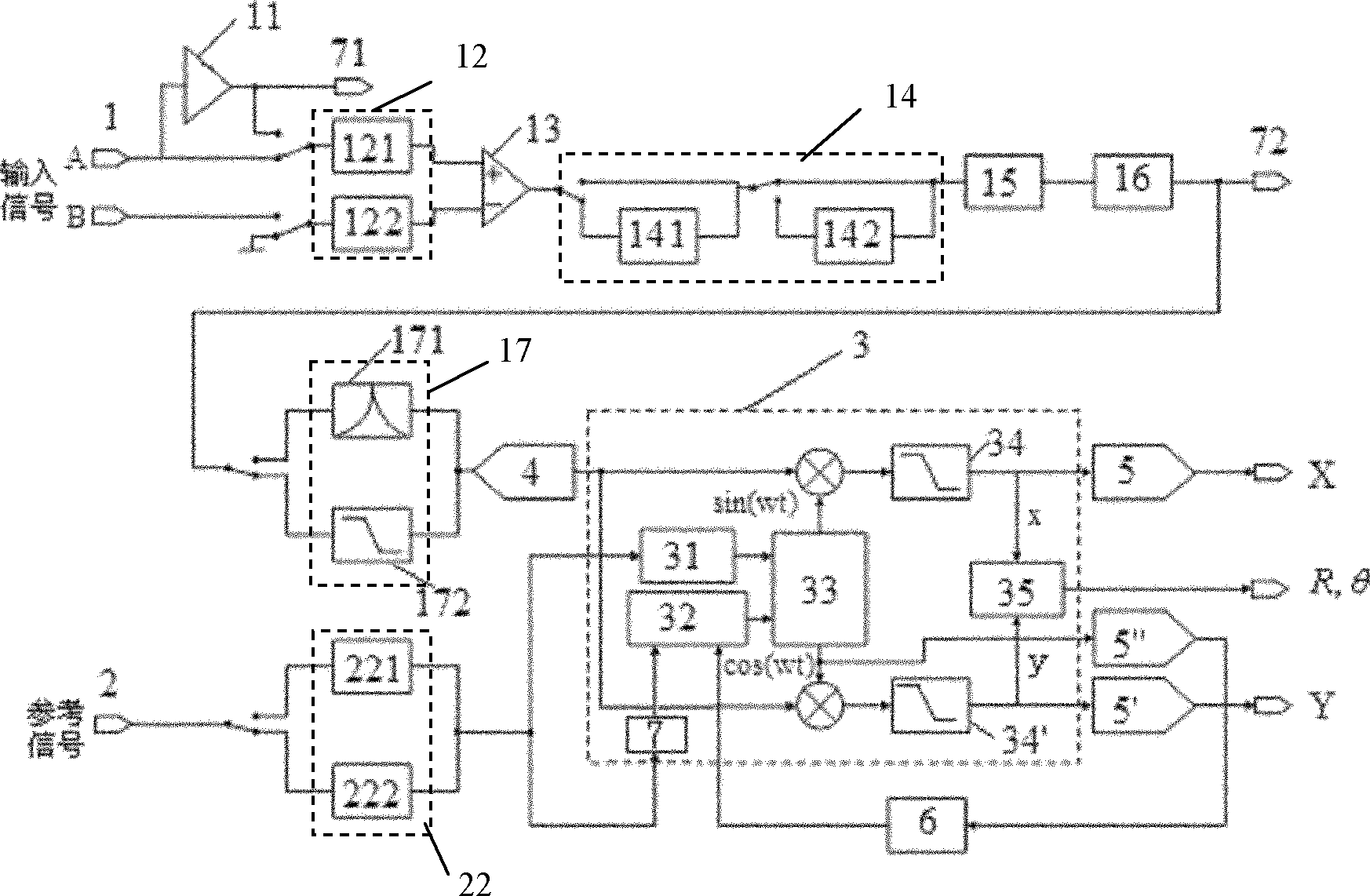
[0031] see figure 2 The digital lock-in amplifier shown includes signal channel 1, reference channel 2 and signal processor 3. The signal to be tested is input from the signal channel 1, and the current and voltage conversion, amplification and filtering are performed in the signal channel 1. Subsequently, the signal is converted into a digital signal by the A / D converter 4 and input to the signal processor 3, which is processed by a programmable logic controller (FPGA) in this embodiment. After the reference signal is shaped by the reference channel 2, it can be input to the signal processor 3 as a square wave signal or a sine wave signal. The signal to be measured and the reference signal are processed by the signal processor 3 to form two outputs, which are converted into analog outputs of the X channel and the Y channel through tw...


PUM


Abstract

The invention discloses a digital phase lock amplifier which comprises a signal passage (1), a reference passage (2) and a signal processor (3), wherein the signal passage (1) is connected with the signal processor (3) through an analog to digital converter (4); the signal processor (3) comprises a frequency measurement module (31), a phase detection discriminator (32), a Cordic generator (33), and a first low pass filter (34) and a second low pass filter (34'). The reference passage (2) forms two paths to output to the signal processor (3) through a signal shaping circuit module (22); one path of the reference passage (2) is input to the Cordic generator (33) through the frequency measurement module (31), and the other path of the reference passage (2) is input to the Cordic generator (33) through a phase shifting module (7) and the phase detection discriminator (32); and the sine and cosine signals output by the Cordic generator (33) are multiplied by the input signal of the signal passage (1) respectively, and are output through the first and second low pass filters (34 and 34') and digital to a first D/A converter (5) and a second D/A converter (5') in sequence. Compared with the prior art, the digital phase lock amplifier has the advantages of high precision, wide frequency band and stable data, and improves the phase precision and eliminates the frequency nonlinearity of an analog channel.

Description

technical field [0001] The invention relates to the field of weak signal detection and amplification equipment, in particular to a digital lock-in amplifier based on a cross-correlation algorithm. Background technique [0002] Lock-in amplification technology is the most widely used and most effective method in weak signal detection. The basic idea of ​​lock-in amplification technology to measure weak signals mainly has two points. One is to use the reference signal to modulate the slow-changing or DC signal to realize frequency migration. Due to the existence of a large amount of noise in the daily environment, these noises have a certain distribution in the frequency domain, and the noise has a larger amplitude in the low frequency stage. If the frequency of the signal to be measured is low or a DC signal, the noise will inevitably be amplified when the measurement signal is amplified. If the AC amplification is used, these noise frequency areas with large amplitude can...

Claims


Application Information

Patent Timeline
IPC IPC(8): H03F7/00H03L7/00
Inventor 王自鑫何振辉蔡志岗胡庆荣徐辉
Owner SUN YAT SEN UNIV
Why Eureka
Try Eureka