Sliding element, method of manufacturing the sliding element, and bearing device using the sliding element

A sliding material, sliding surface technology, used in sliding contact bearings, bearings in rotary motion, bearings, etc., to achieve the effect of simple manufacturing equipment, preventing thermal degradation, and offsetting shear stress

Active Publication Date: 2011-05-04
KK TOSHIBA
View PDF11 Cites 3 Cited by
  • Summary
  • Abstract
  • Description
  • Claims
  • Application Information

AI Technical Summary

Problems solved by technology

However, this method requires a large-scale manufacturing facility, thus causing problems in operability

Method used


Image

  • Sliding element, method of manufacturing the sliding element, and bearing device using the sliding element
  • Sliding element, method of manufacturing the sliding element, and bearing device using the sliding element
  • Sliding element, method of manufacturing the sliding element, and bearing device using the sliding element

Examples


Embodiment 1

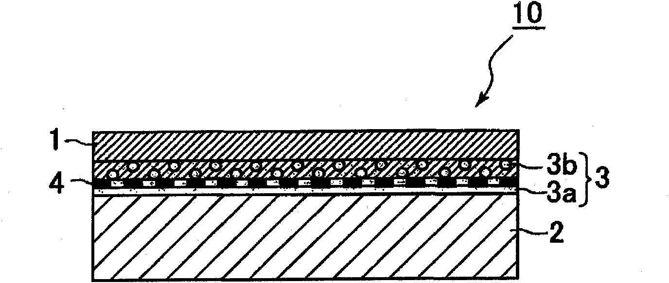
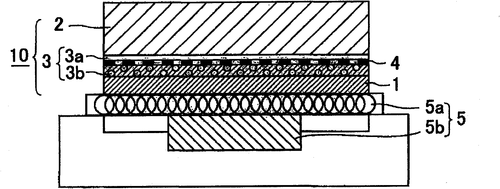
[0081] use as figure 2The arrangement shown produces a sliding material 10 according to the invention. Specifically, first, polytetrafluoroethylene (PTFE) resin material powder (average particle diameter of about 35 μm, melting point of about 327° C.) was introduced into a mold having a rectangular opening with a size of 300 mm×300 mm in an amount such that The thickness of the sliding surface member 1 is 13 mm, and the polytetrafluoroethylene resin material is the material of the sliding surface member 1 . Then, the same polytetrafluoroethylene (PTFE) resin material powder was mixed with Sn powder containing 0.7 wt % Cu (average particle diameter of about 50 μm, melting point of about 227° C.) used as a bonding material at a volume ratio of 1:1. The mixed powder mixture, which is the material of layer 3b, is introduced into the mold in such an amount that the resulting layer 3b has a thickness of 1 mm. Then, a 20-mesh pure iron flat-woven wire mesh used as a porous sheet m...


PUM

PropertyMeasurementUnit
thicknessaaaaaaaaaa
thicknessaaaaaaaaaa
widthaaaaaaaaaa

Abstract

A sliding element comprises a sliding surface member, a base made of a material different from that of the sliding surface member, a joining material layer which is disposed between the sliding surface member and the base and joins the sliding surface member and the base to each other, and a sheet member made of an electromagnetic induction heating material. The sliding surface member and the base are joined to each other by heating and melting the joining material layer by means of electromagnetic induction heating of the sheet member.

Description

technical field [0001] The present invention relates to a sliding material suitable for use in a sliding part of a bearing device, a method of manufacturing the sliding material, and a bearing device using the sliding material. Background technique [0002] Recently, with the advancement of industrial technology, bearings capable of high-speed operation and capable of providing high surface pressure are required. Sliding materials traditionally used to form sliding parts of bearing devices are soft metal materials, such as white metals (for example, the first type contains 88-92% by weight of Sn, 5-7% by weight of Sb, and 3-5% by weight of Cu). However, such soft metal materials have a low melting point, and the strength and seizure at high temperatures are significantly deteriorated, so their use and applicable range are limited. [0003] In contrast, a polytetrafluoroethylene (PTFE) resin material has a low coefficient of friction and high heat resistance, thereby being ...

Claims


Application Information

Patent Timeline
Patent Type & Authority Applications(China)
IPC IPC(8): F16C33/20
CPCF16C17/02F16C17/04F16C33/201F16C2300/14F16C2380/26Y10T428/24331Y10T442/339Y10T442/655Y10T428/31504Y10T428/31721Y10T428/31678Y10T428/3154F16C2208/32
Inventor 龙谈荣久里裕二南波聪向井一马
Owner KK TOSHIBA
Why Eureka
Try Eureka