Sliding element, method of manufacturing sliding element, and bearing device using sliding element

一种滑动材料、滑动表面的技术,应用在滑动接触轴承、旋转运动的轴承、轴承等方向,达到提高剪切强度、改善结合质量、简单制造设备的效果

Active Publication Date: 2013-12-18
KK TOSHIBA
View PDF1 Cites 0 Cited by
  • Summary
  • Abstract
  • Description
  • Claims
  • Application Information

AI Technical Summary

Problems solved by technology

However, this method requires a large-scale manufacturing facility, thus causing problems in operability

Method used


Image

  • Sliding element, method of manufacturing sliding element, and bearing device using sliding element
  • Sliding element, method of manufacturing sliding element, and bearing device using sliding element
  • Sliding element, method of manufacturing sliding element, and bearing device using sliding element

Examples


Embodiment 1

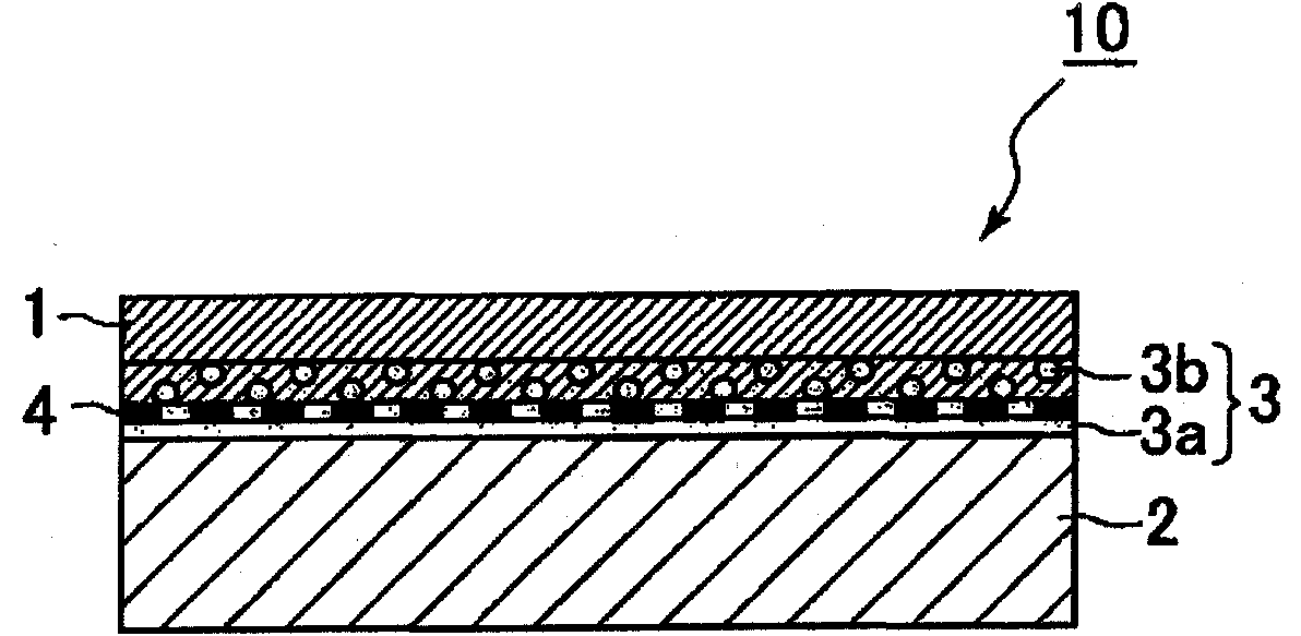
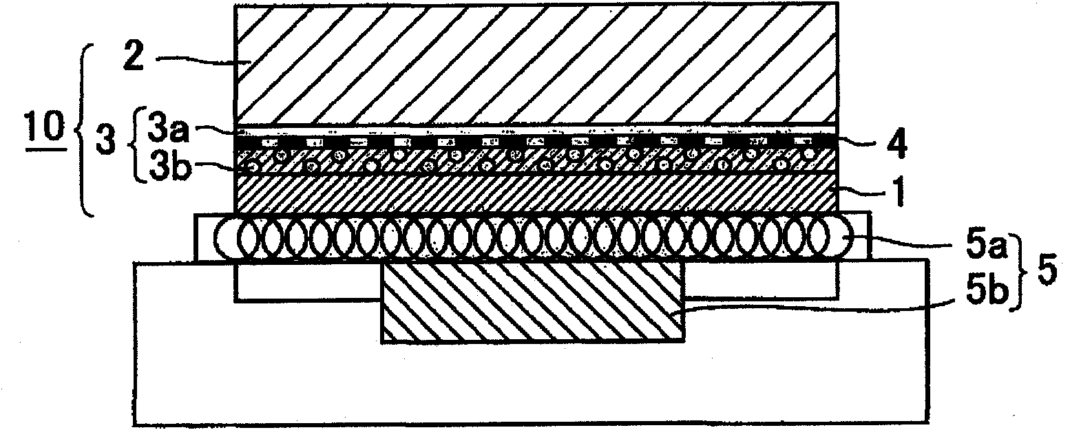
[0081] use as figure 2The arrangement shown produces a sliding material 10 according to the invention. Specifically, first, polytetrafluoroethylene (PTFE) resin material powder (average particle diameter of about 35 μm, melting point of about 327° C.) was introduced into a mold having a rectangular opening with a size of 300 mm×300 mm in an amount such that The thickness of the sliding surface member 1 is 13 mm, and the polytetrafluoroethylene resin material is the material of the sliding surface member 1 . Then, the same polytetrafluoroethylene (PTFE) resin material powder was mixed with Sn powder containing 0.7 wt % Cu (average particle diameter of about 50 μm, melting point of about 227° C.) used as a bonding material at a volume ratio of 1:1. The mixed powder mixture, which is the material of layer 3b, is introduced into the mold in such an amount that the resulting layer 3b has a thickness of 1 mm. Then, a 20-mesh pure iron flat-woven wire mesh used as a porous sheet m...


PUM


Abstract

A sliding material includes a sliding surface member, a base member made of a material different from the sliding surface member, a bonding material layer disposed between the sliding surface member and the base member so as to bond the sliding surface member and the base member, and a sheet member made of an electromagnetic induction heating material. The sliding material is manufactured by bonding the sliding surface member and the base member by heating and melting the bonding material layer through electromagnetic induction heating of the sheet member.

Description

technical field [0001] The present invention relates to a sliding material suitable for use in a sliding part of a bearing device, a method of manufacturing the sliding material, and a bearing device using the sliding material. Background technique [0002] Recently, with the advancement of industrial technology, bearings capable of high-speed operation and capable of providing high surface pressure are required. Sliding materials traditionally used to form sliding parts of bearing devices are soft metal materials, such as white metals (for example, the first type contains 88-92% by weight of Sn, 5-7% by weight of Sb, and 3-5% by weight of Cu). However, such soft metal materials have a low melting point, and the strength and seizure at high temperatures are significantly deteriorated, so their use and applicable range are limited. [0003] In contrast, a polytetrafluoroethylene (PTFE) resin material has a low coefficient of friction and high heat resistance, thereby being ...

Claims


Application Information

Patent Timeline
Patent Type & Authority Patents(China)
IPC IPC(8): F16C33/20
CPCF16C2300/14F16C17/04F16C33/201F16C17/02F16C2380/26Y10T428/24331Y10T442/339Y10T442/655Y10T428/31504Y10T428/31721Y10T428/31678Y10T428/3154F16C2208/32
Inventor 龙谈荣久里裕二南波聪向井一马
Owner KK TOSHIBA
Why Eureka
Try Eureka