Clamp for shaft parts and clamping device

A technology for shaft parts and clamping devices, applied in positioning devices, metal processing mechanical parts, clamping and other directions, can solve the problems of affecting the total processing time, reducing production efficiency, short processing time, etc., and achieving a simple and practical structure. , High production efficiency, firm clamping effect

Inactive Publication Date: 2011-05-11
福昌精密制品(深圳)有限公司
View PDF4 Cites 17 Cited by
  • Summary
  • Abstract
  • Description
  • Claims
  • Application Information

AI Technical Summary

Problems solved by technology

[0002] In actual production, the second processing of shaft parts often occurs: such as offset, square pin, ellipse and other steps; when the size of the part is small, the time for processing is relatively short, and a lot of time is consumed in the assembly For auxiliary operations such as clamping and tool setting, for a certain mass production, the degree of automation of clamping will seriously affect the total time of the processing process and reduce production efficiency

Method used


Image

  • Clamp for shaft parts and clamping device
  • Clamp for shaft parts and clamping device
  • Clamp for shaft parts and clamping device

Examples


Embodiment Construction

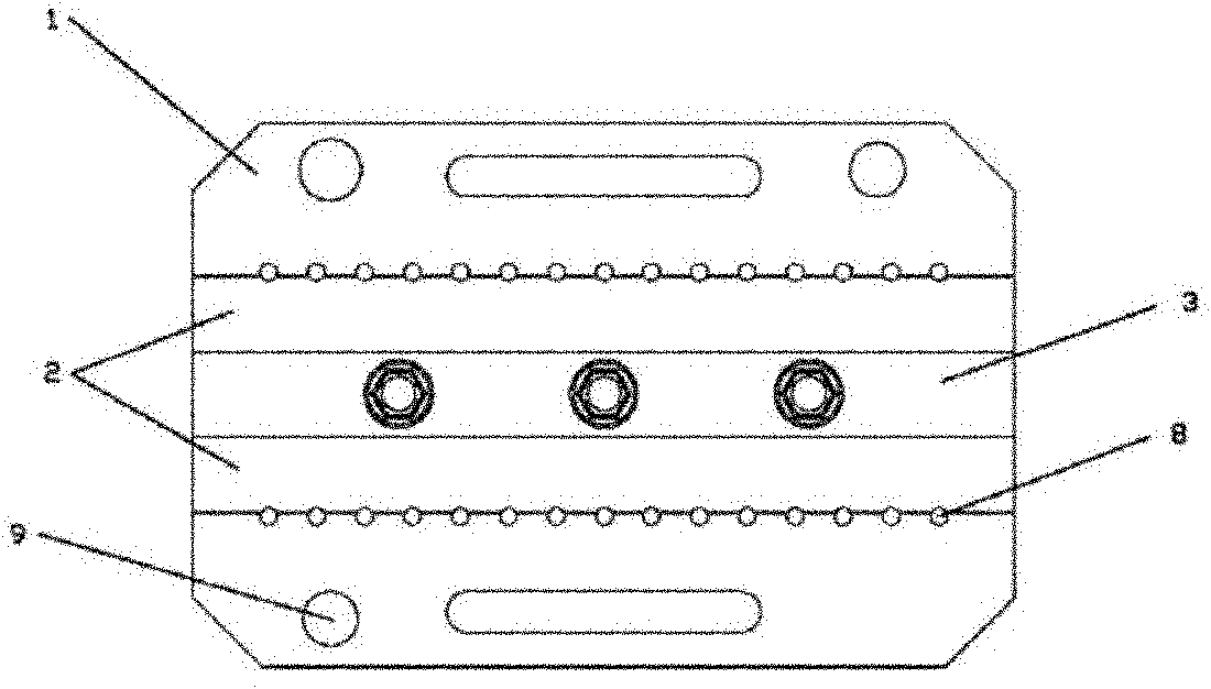
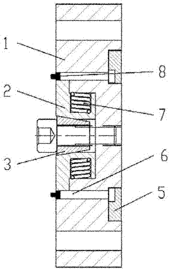
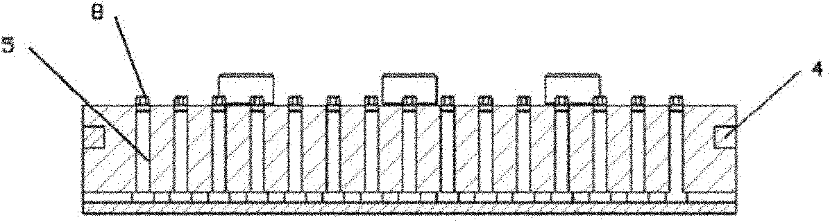
[0026] like figure 1 , 2 Said, a fixture for shaft parts, the fixture includes a positioning plate 1, a slider 2 installed in the chute of the positioning plate 1, a locking block 3 matched with the slider 2, so that The slide block 2 generates the return spring 7 of the reset force, and the workpiece 8 installed on the positioning plate 1 through the positioning pin 6; the slide block 2 is two and symmetrically distributed on the locking block one 3 and the locking block 3 directly or indirectly conflicts with the slider 2; the positioning pin 6 is fixedly installed in the positioning hole of the positioning plate 1 through the pressing block 5 Inside, the positioning pins 6 are multiple and distributed on both sides of the positioning plate 1. In this embodiment, the positioning pins are divided into two rows and evenly distributed on both sides of the positioning plate, and each There are fifteen positioning pins in a row, and the positioning pins are matched with the wor...


PUM


Abstract

The invention relates to a clamp for shaft parts, which is characterized by comprising a positioning plate, a sliding block arranged in a sliding groove of the positioning plate, a locking block I matched with the sliding block, a restoring spring for allowing the sliding block to generate restoring force and a workpiece arranged on the positioning plate by a positioning needle, wherein the locking block I allows the sliding block to slide towards both edges to clamp the workpiece on the positioning plate in the locking state; and in the loosening state of the locking block I, the sliding block restores inwards to loosen the workpiece by the restoring force generated by the restoring spring, so that the workpiece is disassembled and replaced. A plurality of sets of clamps are fixedly arranged on a positioning base of the clamping device, so that the problems of the positioning and clamping of the shaft parts with the diameters of between 1.5 and 10 millimeters are solved effectively; and the machining, assembly or disassembly can be performed simultaneously on the clamp, and the clamp has high production efficiency, accurate positioning, firm clamping and a simple and practical structure, and is suitable for batch production.

Description

technical field [0001] The invention relates to a clamp for shaft parts, and more to a clamping device with the clamp. Background technique [0002] In actual production, the second processing of shaft parts often occurs: such as offset, square pin, ellipse and other steps; when the size of the part is small, the time for processing is relatively short, and a lot of time is consumed in the assembly For auxiliary operations such as clamping and tool setting, for a certain mass production, the degree of automation of clamping will seriously affect the total time of the processing process and reduce production efficiency. Contents of the invention [0003] The object of the present invention is to provide a fixture for shaft parts, which has precise positioning, firm clamping, simple and practical structure; [0004] Another object of the present invention is to provide a clamping device, which can be loaded or unloaded and processed at the same time, which fully utilizes th...

Claims


Application Information

Patent Timeline
Patent Type & Authority Applications(China)
IPC IPC(8): B23Q3/06
Inventor 罗国军曾冠平
Owner 福昌精密制品(深圳)有限公司
Why Eureka
Try Eureka