Shock absorber

A technology of buffers and cylinders, applied in the direction of shock absorbers, shock absorbers, gas-hydraulic shock absorbers, etc., to achieve the effect that is not easy to transmit

Inactive Publication Date: 2011-05-11
HITACHI AUTOMOTIVE SYST LTD
View PDF8 Cites 8 Cited by
  • Summary
  • Abstract
  • Description
  • Claims
  • Application Information

AI Technical Summary

Problems solved by technology

[0005] However, in the structure described in the above-mentioned Patent Document 1, there is a problem that when the rebound spring vibrates, the vibration and noise are transmitted to the vehicle body via the spring support directly fixed to the piston rod.

Method used


Image

  • Shock absorber
  • Shock absorber
  • Shock absorber

Examples


Embodiment Construction

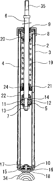
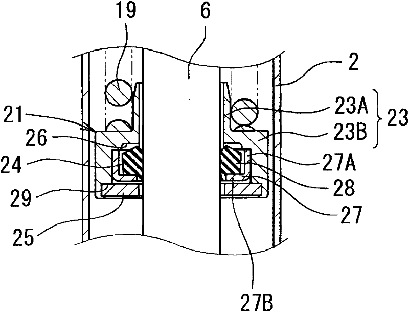
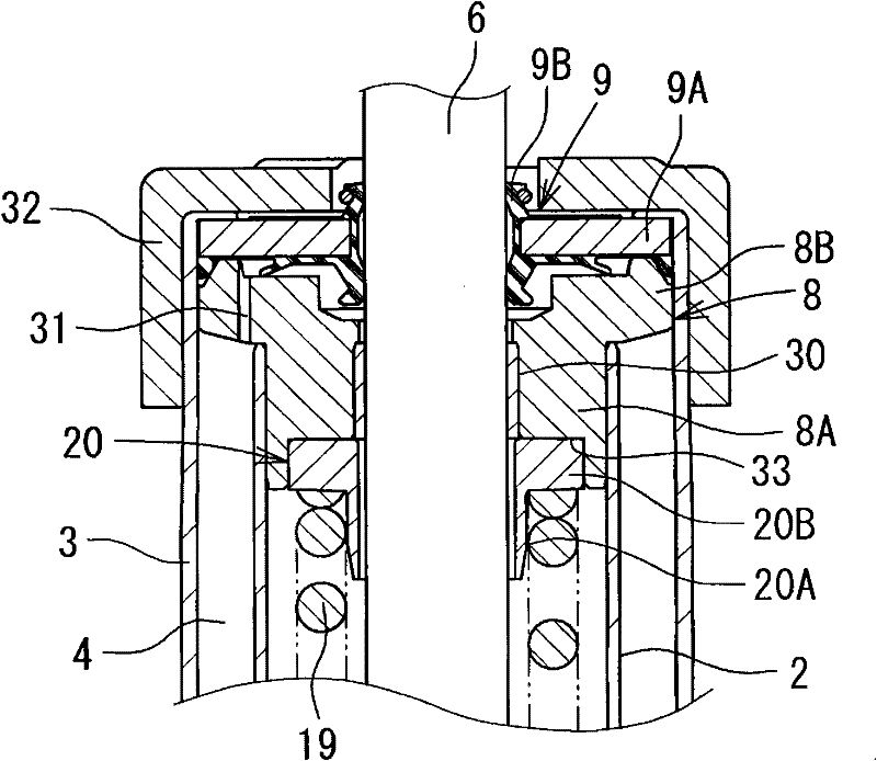
[0021] Hereinafter, embodiments of the present invention will be described in detail based on the drawings. Such as figure 1 As shown, the shock absorber of this embodiment, that is, the hydraulic shock absorber 1 is an upright double-tube hydraulic shock absorber, and an outer cylinder 3 is formed on the outer periphery of the cylinder 2, and a storage space is formed between the cylinder 2 and the outer cylinder 3. The double cylinder structure of device 4. A piston 5 is slidably fitted in the cylinder 2, and the piston 5 divides the interior of the cylinder 2 into two chambers: a cylinder upper chamber 2A and a cylinder lower chamber 2B. One end of the piston rod 6 is connected to the piston 5 through the nut 7, and the other end of the piston rod 6 is inserted into the rod guide 8 and the oil seal 9 installed on the upper end of the cylinder 2 and the outer cylinder 3, and they are penetrated from the upper end of the cylinder 2 to the outside. protrude. The other end s...


PUM


Abstract

The invention relates to a hydraulic shock absorber which can rebound spring vibration to prevent the noise from being transmitted to the vehicle body side. a piston (5) connected with a piston rod (6) is inserted into the a cylinder filled with oil in a slidable waby; the stroke of the piston rod (6) is applied with a attenuation force generated by a elongating side, a shortening side attenuation force generation mechanism (13, 14) and a attenuation force generation mechanism (18). A rebounding spring (19) is disposed around the piston rod (6) inside the cylinder (2); one end of the spring is fixedly mounted on a rod guiding element (8) of the cylinder (2), the other end is free. A spring guiding element (21) having a flexible assembly (24) is mounted on the free end of the rebounding spring (19) while the flexible assembly (24) is arranged in sliding contact with the piston rod (6). The flexible assembly (24) absorbs the vibrations and noises of the rebounding spring (19) to inhibit the vibrations and noises from being transmitted to the vehicle body side by the piston rod (6) easily.

Description

technical field [0001] The present invention relates to a shock absorber mounted on a suspension device or the like of a vehicle. Background technique [0002] A cylindrical hydraulic shock absorber mounted on a suspension device of a vehicle such as a motor vehicle is, for example, described in Patent Document 1. A rebound spring is provided to relax the rebound stopper fixed to the piston side and the Impact and crashing sound when the rod guide fixed to the end of the cylinder collides. The rebound spring is a coil spring inserted around the piston rod between the rebound stopper and the rod guide. When the piston rod is elongated, it starts to compress before the maximum elongation, and uses its elastic force to reduce the piston speed and ease the damage caused by the maximum elongation. The impact and collision sound caused by the collision at the time. [0003] Patent Document 1: (Japanese) Unexamined Patent Publication No. 2004-124993 [0004] Patent Document 2: (...

Claims


Application Information

Patent Timeline
Patent Type & Authority Applications(China)
IPC IPC(8): F16F9/58F16F9/32F16F9/00F16F9/06
CPCF16F9/3242F16F9/363F16F9/585
Inventor 构良介
Owner HITACHI AUTOMOTIVE SYST LTD
Why Eureka
Try Eureka