
Periscopic image measurement instrument

An image measuring instrument and periscope technology, applied in the field of image measuring instruments, can solve the problems of large limitations, inability to measure the inner wall of holes, and limit the application scope of the image measuring instrument, and achieve the effect of broadening the application scope.

Active Publication Date: 2012-02-15
TZTEK TECH
View PDF0 Cites 0 Cited by
  • Summary
  • Abstract
  • Description
  • Claims
  • Application Information

AI Technical Summary

Problems solved by technology

[0002] The image measuring instrument is an emerging geometric quantity measuring instrument, which can efficiently complete the measurement of two-dimensional dimensions. Compared with the traditional contact coordinate measuring machine, the image measuring instrument has absolute advantages in the measurement of two-dimensional plane dimensions, but due to It is limited to two-dimensional measurement and simple height measurement, which severely limits the application range of image measuring instruments
[0003] At present, the image measuring instrument needs to use auxiliary means such as prisms to measure the side wall. This method has great limitations. It is necessary to place prisms at various positions to be measured, and it cannot realize the measurement of the inner wall of the hole.
[0004] In the literature in recent years, no reports have been found to solve this problem

Method used


Image

  • Periscopic image measurement instrument
  • Periscopic image measurement instrument
  • Periscopic image measurement instrument

Examples


Embodiment Construction

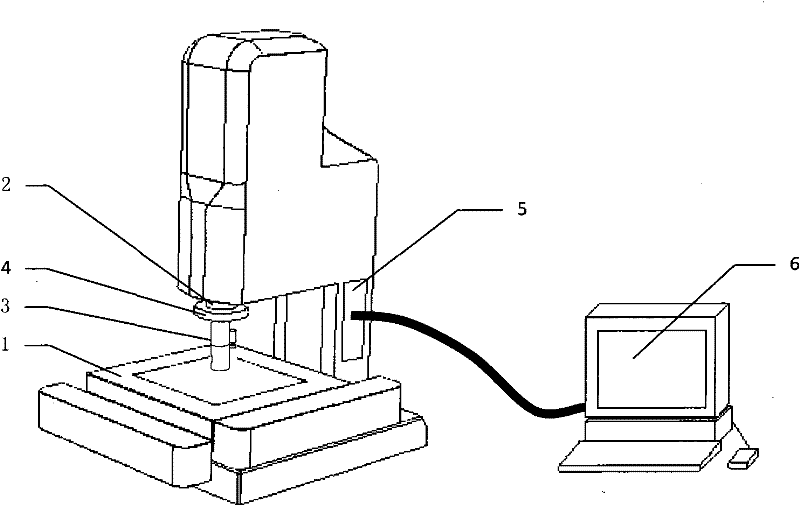
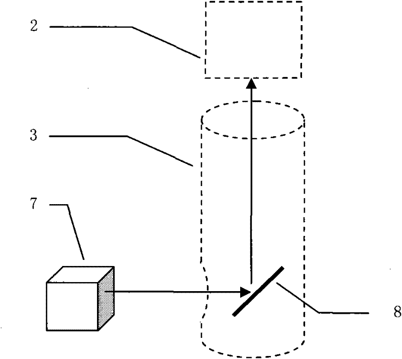
[0018] The periscope image measuring instrument is based on a three-axis CNC mobile table [1], equipped with a microscope [2], a periscope objective lens [3], a CCD, a lighting system [4], an electrical control card [5] and a personal computer [ 6].

[0019] The three-axis CNC automatic mobile workbench [1] is divided into XY mobile platform and Z axis, the XY mobile platform is used to carry the workpiece to be measured, the microscope [2] is fixed on the Z axis, and the periscope objective lens [3] is fixed at the lower end of the microscope. The up and down movement of the Z axis can control the focus sharpness of the microscope. The three axes of XYZ are composed of linear guide rail, ball screw and DC servo control system, which can obtain very high positioning accuracy. The three-axis workbench can be controlled by the computer and driven by the electrical control card [5] to realize program control and meet the needs of automatic measurement.

[0020] The personal com...


PUM


Abstract

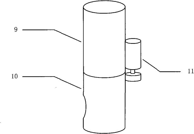
The invention discloses a periscopic image measurement instrument. The periscopic image measurement instrument takes a triaxial CNC (Computerized Numerical Control) moving working table as a main body and is provided with a microscope, a periscope eyepiece, a CCD (Charge Coupled Device), a lighting system, an electrical control card and a personal computer. The triaxial moving working table can be controlled by the computer to be driven by the electrical control card to realize programmed control. The personal computer is provided with an image acquisition card to receive a workpiece image acquired by an optical imaging system comprising the microscope and the CCD. The periscope eyepiece is arranged at the lower end of the microscope and comprises a connecting pipe, a prism assembly and atransmission assembly. The prism assembly takes a prism as a main body and is externally provided with fixed, connected and rotated parts. The transmission assembly comprises a micromotor and a gear,the main body of the micromotor is fixed with the connecting pipe, a drive gear is fixed on a motor shaft, and the drive gear is directly engaged with the gear of the prism assembly. The micromotor drives the prism assembly to rotate to adjust orientation of a reflecting surface of the prism when the micromotor is rotated.

Description

technical field [0001] The invention is a special image measuring instrument, which solves the problem that ordinary image measuring instruments cannot measure the side wall of a workpiece and the inner wall of a hole by adopting a periscope objective lens, and greatly broadens the application range of the image measuring instrument. Background technique [0002] The image measuring instrument is an emerging geometric quantity measuring instrument, which can efficiently complete the measurement of two-dimensional dimensions. Compared with the traditional contact coordinate measuring machine, the image measuring instrument has absolute advantages in the measurement of two-dimensional plane dimensions, but due to It is limited to two-dimensional measurement and simple height measurement, which seriously limits the application range of the image measuring instrument. [0003] At present, the image measuring instrument needs to use auxiliary means such as prisms to measure the s...

Claims


Application Information

Patent Timeline
Patent Type & Authority Patents(China)
IPC IPC(8): G01B11/00G02B13/00
Inventor 杨聪徐一华
Owner TZTEK TECH
Learn More