
Scanner device and method for computed tomography imaging

A technology of tomography, scanning methods, applied in the direction of computerized tomography scanners, instruments for radiological diagnosis, diagnosis

Inactive Publication Date: 2013-03-27
健康与环境慕尼黑德国研究中心赫姆霍茨中心(有限公司)
View PDF5 Cites 0 Cited by
  • Summary
  • Abstract
  • Description
  • Claims
  • Application Information

AI Technical Summary

Problems solved by technology

Another drawback of fourth-generation CT scanners is due to the non-uniformity of the X-ray geometry
However, this covers only a limited range of projection angles, so reconstruction of the complete tomographic image is not possible with tomosynthesis imaging

Method used


Image

  • Scanner device and method for computed tomography imaging
  • Scanner device and method for computed tomography imaging
  • Scanner device and method for computed tomography imaging

Examples


Embodiment Construction

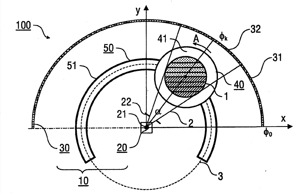
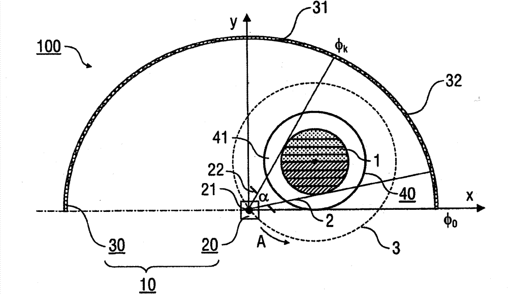
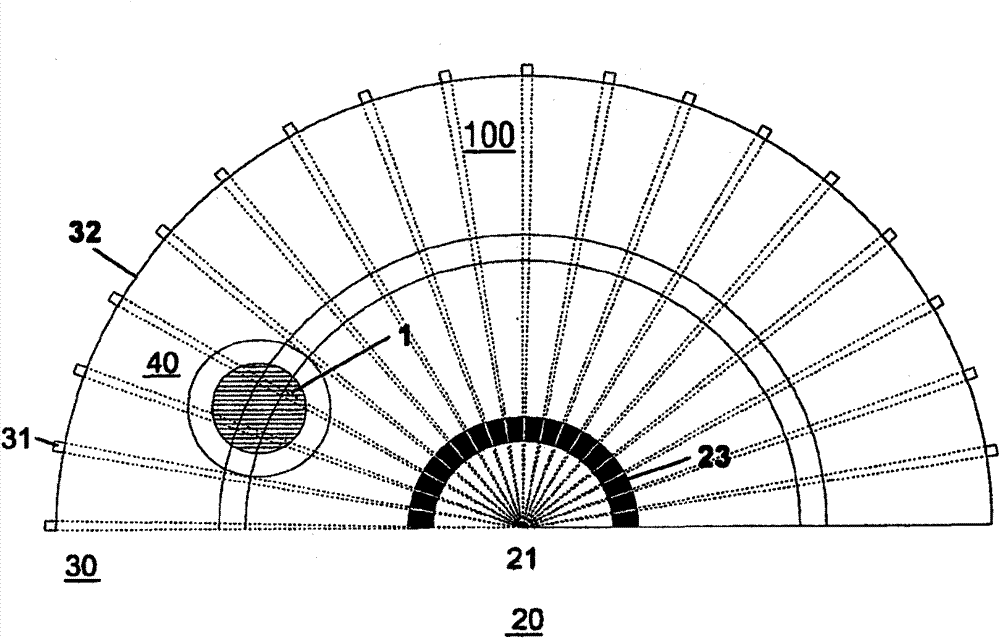
[0041] Embodiments of the invention are described below, in particular with reference to the geometry of the CT scanner according to the invention and the procedural steps of the scanning method for collecting attenuation data for CT imaging. Details of CT equipment, in particular control equipment, display equipment, power supply equipment, details of controlling X-ray tubes, detecting X-rays, processing collected attenuation data and reconstructing 2D or 3D CT of an object or some part of it The details of the images are not presented here, as these are known from conventional CT techniques.

[0042] Furthermore, the following description of the preferred embodiment refers to detector elements along a semicircle ( figure 1 , 2) or polygon line ( Figure 5 ) arrangement or fan beam elements along a semicircle ( Figure 7 ) layout form. It is important to emphasize that the invention is not limited to these respective arrangements of detectors or fan beam elements. As an ...


PUM

PropertyMeasurementUnit
thicknessaaaaaaaaaa

Abstract

A scanner device (100) for computed tomography imaging of an object (1), comprises a measurement device (10) including a source device (20) arranged for irradiating the object (1) with at least one beam (2) and a detector device (30) arranged for detecting radiation transmitted through the object (1), wherein the source device (20) has a fixed position relative the detector device (30), and a carrier device (40) accommodating the object (1) in a position between the source device (20) and the detector device (30), wherein the measurement device (10) and the carrier device (40) are capable of a scanning movement relative to each other, and the measurement device (10) and the carrier device (40) have a fixed spatial orientation during the scanning movement. Furthermore, a scanning method for computed tomography imaging of an object is described.

Description

technical field [0001] The present invention relates to a scanner device for performing computed tomography (CT) imaging on a target object, in particular to a scanner device comprising a measuring device with source and detector devices and a carrying device for accommodating the target object, In this case the measuring device and the carrier device can be moved relative to each other in a scanning manner. Furthermore, the present invention relates to a scanning method for performing CT imaging of an object. Scanner devices and scanning methods can be used for all applications of CT imaging, especially in the fields of material science, medical examination, construction technology, technology concerning safety issues, etc. Background technique [0002] CT imaging is based on the irradiation of the object to be investigated. The X-rays generated by the source device are used to irradiate the sampling plane from different projection directions, and then the sampling plane i...

Claims


Application Information

Patent Timeline
Patent Type & Authority Patents(China)
IPC IPC(8): A61B6/03G01N23/04
CPCA61B6/0457A61B6/032G01N23/046A61B6/4028A61B6/04G01N2223/419A61B6/0487
Inventor O·蒂申科M·克拉夫顿C·赫申M·赫劳贝德安杰利斯
Owner 健康与环境慕尼黑德国研究中心赫姆霍茨中心(有限公司)
Learn More