Gear measuring system, gear measuring method and special handheld movable optical reverse reflector

A gear measurement and reflector technology, applied in the direction of using optical devices, measuring devices, measuring/indicating equipment, etc., can solve the problems of adverse effects of measurement results, and the accuracy cannot meet the requirements of such gear measurement, and achieve the effect of improving the manufacturing level.

Active Publication Date: 2011-05-18
CHINA ERZHONG GRP DEYANG HEAVY IND +3
View PDF9 Cites 12 Cited by
  • Summary
  • Abstract
  • Description
  • Claims
  • Application Information

AI Technical Summary

Problems solved by technology

[0008] It can be seen that the accuracy of large-scale spatial coordinate measurement using laser trackers cannot meet the measurement requirements of such gears
[0009] Secondly, the three-coordinate measurement unit uses a mechanical contact sensor, which is easy to adversely affect the measurement results

Method used


Image

  • Gear measuring system, gear measuring method and special handheld movable optical reverse reflector
  • Gear measuring system, gear measuring method and special handheld movable optical reverse reflector
  • Gear measuring system, gear measuring method and special handheld movable optical reverse reflector

Examples


Embodiment 1

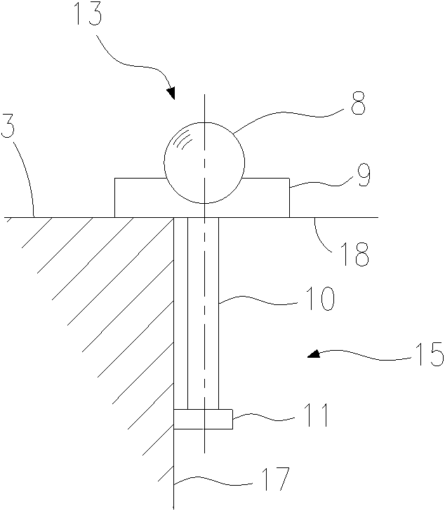
[0058] Such as Figure 5 As shown, the positioning body 15 is a long cylindrical structure with the positioning seat 9 installed on one upper end and coaxial with the reflector 8 . In use, the outer cylindrical surface of the elongated cylindrical structure is tangent to the inner cylindrical surface of the hole wall of the central hole 17 of the gear 3 to be tested for radial positioning. Since the tangent between the outer cylindrical surface of the long cylindrical structure and the inner cylindrical surface of the hole wall of the central hole 17 of the gear 3 under test is in most cases a straight line, the straightness error will have a certain impact on the measurement results.

Embodiment 2

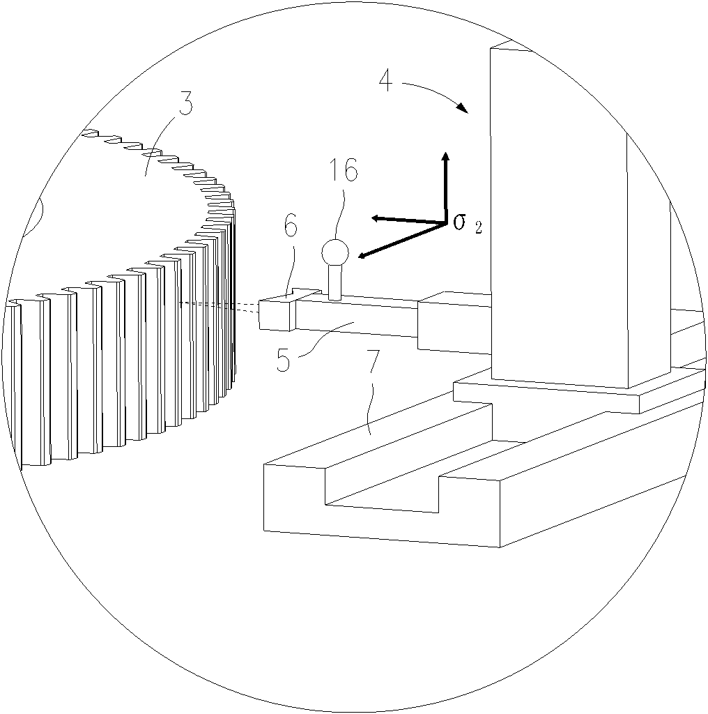
[0060] Such as Image 6 As shown, the positioning body 15 includes a support rod 10 on which the positioning seat 9 is installed at the upper end, and a rotating body 11 arranged at the lower end of the supporting rod 10, and the positioning body 15 is connected to the measured gear through the rotating body 11 The hole wall of the central hole 17 of 3 is in contact, and the rotating body 11 is arranged coaxially with the reflector 8; wherein, the rotating body 11 is spherical. During the measurement, the rotating body 11 is in point contact with the inner cylindrical surface of the hole wall of the central hole 17 of the gear 3 under test, so the contact point may be located at the contour peak or contour valley of the surface roughness of the hole wall, so the measured The surface roughness of the hole wall of the central hole 17 of the gear 3 will have a certain influence on the measurement result.

Embodiment 3

[0062] Such as image 3 As shown, the positioning body 15 includes a support rod 10 on which the positioning seat 9 is installed at the upper end, and a rotating body 11 arranged at the lower end of the supporting rod 10, and the positioning body 15 is connected to the measured gear through the rotating body 11 The hole walls of the central hole 17 of 3 are in contact with each other, and the rotating body 11 is arranged coaxially with the reflector 8; wherein, the rotating body 11 is disc-shaped. In this way, the rotating body 11 and the inner cylindrical surface of the hole wall of the central hole 17 of the gear under test 3 are in surface contact with a small contact area, which can avoid the influence of the straightness error on the measurement results in Embodiment 1, It can also avoid the impact of the contact surface roughness on the measurement results in Example 2.


PUM


Abstract

The invention discloses a gear measuring system with high measurement accuracy, a gear measuring method and a special handheld movable optical reverse reflector. The global measuring equipment of the system adopts a multi-path laser interference tracking system which comprises at least three laser interference tracking instruments, a handheld movable optical reverse reflector and a fixed optical reverse reflector, wherein the handheld movable optical reverse reflector is used in match with at least three laser interference tracking instruments so as to carry out the space positioning on a gear to be measured, the fixed optical reverse reflector is used for rigid connection with the movable part of front-end measuring equipment, and the handheld movable optical reverse reflector comprises a reflector and a positioning structure which is connected with the reflector and used for driving the handheld movable optical reverse reflector to move on the datum of the gear to be measured along a special direction. The measuring system and the measuring method can be used for accurately measuring an oversize high-accuracy gear with the diameter of 3000-10000 mm, the minimum modulus of 6 mm and the accuracy at 6 level or above and improve the manufacture level of the oversize high-accuracy gear.

Description

technical field [0001] The invention relates to an in-situ measuring system and a measuring method for extra-large gears. Aiming at the technical difficulties of large measurement space range, subtle and diverse types of measured features, and complex local measurement space during the detection of super-large gears, the measurement system and measurement method adopt a short-distance front end that combines large-scale spatial global measurement and small size A combined measurement system that combines measurements. Background technique [0002] In the field, gears with a diameter greater than 3000 mm are defined as oversized gears. [0003] At present, the largest gear measurement center in the world, the maximum measurable diameter of P300 of Klingelnberg company in Germany is 3000mm. For extra-large gears with a diameter greater than 3000mm, since there is no independent measuring instrument, the only detection method at present is to directly integrate the gear measu...

Claims


Application Information

Patent Timeline
Patent Type & Authority Applications(China)
IPC IPC(8): B23Q17/20B23Q17/24G01B11/24
Inventor 史苏存曲兴华牛维汉林超黄勇段玲
Owner CHINA ERZHONG GRP DEYANG HEAVY IND
Why Eureka
Try Eureka