Microfluidic control chip injection molding die

A microfluidic chip and injection mold technology, applied in the field of injection molding molds, can solve the problems of long production cycle and inability to meet the huge market demand for microfluidic chips, improve light transmittance, solve incomplete replication, and prevent samples The effect of leakage

Inactive Publication Date: 2010-03-03
DALIAN UNIV OF TECH
View PDF0 Cites 11 Cited by
  • Summary
  • Abstract
  • Description
  • Claims
  • Application Information

AI Technical Summary

Problems solved by technology

[0004] At present, the main method of making plastic microfluidic chips is thermocompression molding, but its production cycle is long (3-10min), which cannot meet the potentially huge market demand for microfluidic chips

Method used


Image

  • Microfluidic control chip injection molding die
  • Microfluidic control chip injection molding die
  • Microfluidic control chip injection molding die

Examples


Embodiment Construction

[0018] The present invention will be further described in detail below in conjunction with the accompanying drawings and specific embodiments.

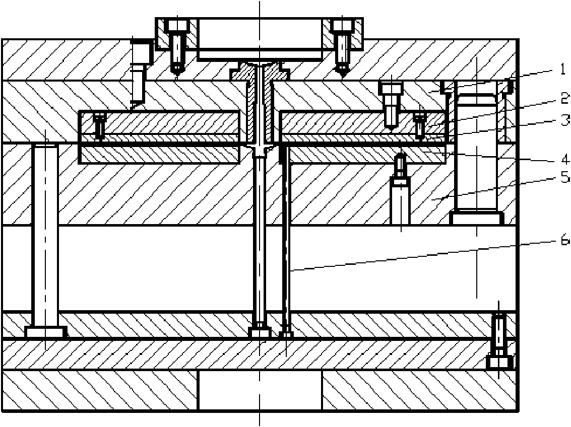
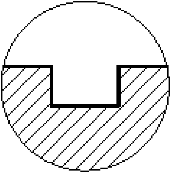
[0019] The injection molding mold of the present invention is used to form the microfluidic chip shown in FIG. 2 .

[0020] Such as figure 1 As shown, the injection molding mold of the present invention has one mold and two cavities, mainly comprising two parts of the injection mold mold frame and the cavity insert, and the cavity insert consists of a fixed mold insert 2, a movable mold insert 4, and a chip for molding. The micro-channel nickel-based microfabrication insert 3 is composed of the fixed mold insert 2 and the fixed template 1 in the mold frame, and is connected by screws; the microfabrication insert 3 is matched with the fixed mold insert 2, and is connected with it by screws Connection, the surface of the microfabrication insert 3 is flat with the surface of the fixed template 1; the movable mold insert 4 cooperates wit...


PUM


Abstract

A microfluidic control chip injection molding die belongs to the technical field of the injection molding die. The injection molding die comprises an injection die die-set part and a cavity insert. The injection die die-set uses a two-plate type injection die die-set; the cavity insert comprises a fixed die insert, a moving die insert and a micro machining insert. The fixed die insert is arrangedin a fixed die plate in a matching way and connected by a bolt; the micro machining insert of a microchannle of a molding chip is arranged in the fixed die insert in the matching way and connected with the fixed die insert; the moving die insert is arranged in a moving die plate in the matching way and connected by the bolt; after compound die, a cavity is formed between the micro machining insertand the moving die insert. The side structure of the cavity of the moving die insert is designed to be a rectangular through groove and has the same size with the chip products. The moving die plateadopts lengthening cross gate and stream-line fan gate design. The injection molding die can mold plastic microfluidic control chip with high efficiency on a large scale, further increases the manufacture level of the microfluidic control chip and promotes the application of the injection molding technology in the micro machinery system field.

Description

technical field [0001] The invention belongs to the technical field of injection molding molds, and in particular relates to an injection molding mold capable of molding microfluidic chips with a microchannel structure on the surface. Background technique [0002] The microfluidic chip integrates the basic operation units involved in the fields of biology and chemistry such as sample preparation, reaction, separation, and detection into a small chip, and forms a microfluidic path under the action of a pressure pump or an electric field to achieve The purpose of high-throughput rapid analysis of samples. At present, it has begun to play an increasingly important role in the fields of analytical chemistry, life sciences and biomedical devices. Micro-analysis systems with micro-fluidic chips as the core are gradually replacing many equipment in the current chemical analysis laboratory, allowing chemical analysis to go out of the laboratory and enter wards, production bases, an...

Claims


Application Information

Patent Timeline
Patent Type & Authority Applications(China)
IPC IPC(8): B29C45/26B29C45/27B29C33/30B29C33/42
Inventor 宋满仓刘莹杜立群王敏杰刘冲
Owner DALIAN UNIV OF TECH
Why Eureka
Try Eureka