Electromagnetically-driven spherical robot

A spherical robot, electromagnetic drive technology, applied in the field of electromechanical, to achieve the effect of simplified drive mode, stable and flexible movement, strong controllability

Inactive Publication Date: 2011-05-18
TAISHAN UNIV
View PDF4 Cites 55 Cited by
  • Summary
  • Abstract
  • Description
  • Claims
  • Application Information

AI Technical Summary

Problems solved by technology

[0006] The purpose of the present invention is to overcome the deficiencies of the existing spherical robot drive mechanism, and provide an electromagnetically driven spherical robot with the advantages of simple structure, reliable mechanism, flexible movement, strong controllability, and easy realization of trajectory planning and control algorithm design.

Method used


Image

  • Electromagnetically-driven spherical robot
  • Electromagnetically-driven spherical robot
  • Electromagnetically-driven spherical robot

Examples


Embodiment 1

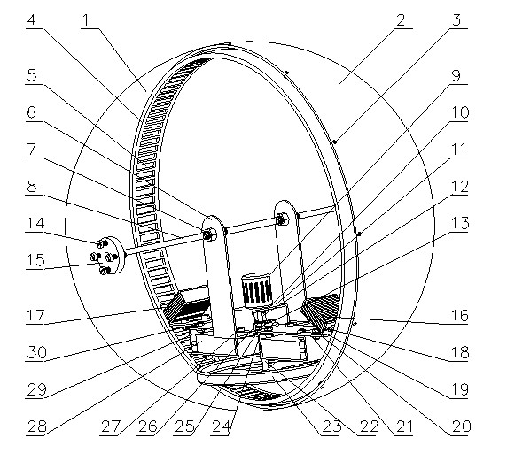
[0026] like figure 1 , 2 , 3, an embodiment of the present invention is: an electromagnetically driven spherical robot, comprising a spherical shell, a magnetic steel ring, and an internal drive structure; the spherical shell is composed of a left hemispherical shell 1 and a right hemispherical shell 2, and The inner wall is equipped with a magnetic steel ring 4, the magnetic steel ring is fixedly connected with the inner wall of the spherical shell and concentric with the spherical shell, the left and right hemispherical shells and the magnetic steel ring are fastened by screws 3, and the permanent magnets 5 are evenly arranged on the magnetic steel ring. The N poles of two adjacent permanent magnet steels or electromagnets face opposite directions; the internal drive structure inside the spherical shell mainly includes: bracket 6, main shaft 8, motor 9, motor bracket 11, and electromagnetic coils arranged symmetrically with respect to main shaft 8 16. The second core elec...

Embodiment approach

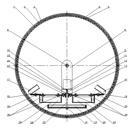
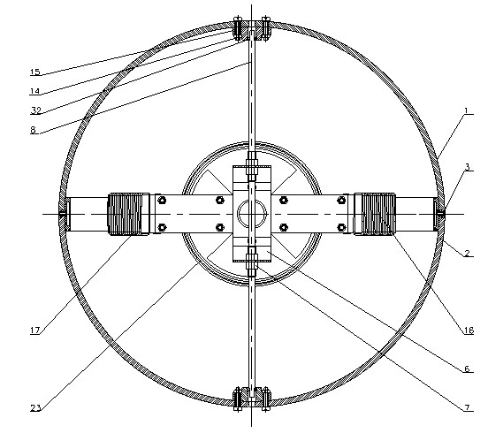
[0029] see Figure 5 Another embodiment of the present invention shown: an electromagnetically driven spherical robot device, comprising a spherical shell, a magnetic steel ring, and an internal drive structure; the spherical shell is composed of a left hemispherical shell 1 and a right hemispherical shell 2, and the The magnetic steel ring 4 is installed, and the magnetic steel ring is fixedly connected with the inner wall of the spherical shell and is concentric with the spherical shell. The left and right hemispherical shells and the magnetic steel ring are fastened by screws 3, and the permanent magnetic steel rings are evenly arranged on the magnetic steel ring. The N poles of two adjacent permanent magnets or electromagnets face opposite directions; the internal drive structure inside the spherical shell mainly includes: bracket 6, main shaft 8, motor 9, motor bracket 11, electromagnetic coil 16. Electromagnetic coil Ⅲ16-1, electromagnetic coil Ⅱ17, electromagnetic coil...


PUM


Abstract

The invention discloses an electromagnetically-driven spherical robot. The electromagnetically-driven spherical robot is characterized in that the spherical robot comprises a spherical case, and magnets uniformly and annularly arranged at the vertical middle positions on the inner wall of the spherical case, wherein adjacent magnets have opposite pole directions; a main shaft is transversely arranged in the spherical case in a rotary manner, and is fixedly connected with a bracket; at least one group of electromagnetic coils are disposed on the bracket; and each electromagnetic coil group includes two pairs of electromagnetic coils arranged symmetrically relative to the main shaft. The magnetic core of the electromagnetic coils can be controlled to attract and repel the magnets on the inner wall of the spherical case by controlling the polarity of the two electromagnetic coils to change alternately, so that the bracket can be driven to rotate around the main shaft; therefore, the spherical robot can move forwards and backwards based on the electromagnetic stepping principle. Compared with the conventional spherical robot, the electromagnetically-driven spherical robot has the advantages of simple and reliable structure, stable and flexible movement, and high controllability. Meanwhile, the driving manner of the spherical robot is simplified greatly in comparison with the existing spherical robot, thereby improving the utilization rate of the inner space of the spherical robot. Spherical robots with different dimensions can be manufactured according to different purposes, thereby enhancing the bearing capacity of the spherical robot, and facilitating the generation of serial products.

Description

technical field [0001] The invention belongs to the field of electromechanical technology, and relates to a mobile spherical robot, in particular to an omnidirectional moving spherical robot device driven by the principle of electromagnetic stepping and conservation of angular momentum. Background technique [0002] A spherical robot is a robot with a spherical shell that walks on a rolling basis. The spherical robot is a breakthrough in the way of robot movement. Its biggest feature is the special way of movement. The spherical shell will enable the robot to obtain the greatest stability after instability. Compared with the wheeled robot that walks on wheels, there is no " Its spherical structure can freely rotate in any direction to realize rolling walking in all directions; compared with walking or crawling robots, it has the characteristics of fast movement speed and strong carrying capacity, and has the characteristics of less driving and simple control . In addition,...

Claims


Application Information

Patent Timeline
Patent Type & Authority Applications(China)
IPC IPC(8): B62D57/02
Inventor 桑胜举沈丁安琦赵继超王军周琼
Owner TAISHAN UNIV
Why Eureka
Try Eureka