Stem cell cryogenic storage device with high internal space utilization rate

A technology of internal space and storage equipment, which is applied to the preservation, application, and animal husbandry of human or animal bodies, and can solve the problems of inconvenient access to stem cell storage vessels, poor thermal insulation effect, and low internal space utilization rate, etc., to achieve Improve the effect of heat preservation, improve the effect of heat insulation and heat preservation, and improve the effect of internal space utilization

Inactive Publication Date: 2018-11-16
NANHUA UNIV
View PDF6 Cites 7 Cited by
  • Summary
  • Abstract
  • Description
  • Claims
  • Application Information

AI Technical Summary

Problems solved by technology

[0002] Most of the existing low-temperature storage devices are stored in the form of liquid nitrogen tanks. In the field of biomedicine, stem cells can be placed in liquid nitrogen tanks for long-term active storage. When needed, they can be used after thawing and rewarming. The patent No. 201620716173.8 discloses a low-temperature storage device for stem cells. An external rotation system and an adiabatic transmission shaft are installed at the middle of the top of the outer container. The adiabatic transmission shaft is connected to the external rotation system. There is a thermal insulation layer, and a sample rotating tray is installed in the inner tank, and the center of the sample rotating tray is connected with the heat-insulating transmission shaft. Bellows are installed between the placement ports, but during the use of the above patents, the utilization rate of the internal space of the storage device is not high, the heat insulation effect is not good, and it is not convenient to take and place the stem cell storage dish

Method used


Image

  • Stem cell cryogenic storage device with high internal space utilization rate
  • Stem cell cryogenic storage device with high internal space utilization rate
  • Stem cell cryogenic storage device with high internal space utilization rate

Examples


Embodiment Construction

[0024] The following will clearly and completely describe the technical solutions in the embodiments of the present invention with reference to the accompanying drawings in the embodiments of the present invention. Obviously, the described embodiments are only some, not all, embodiments of the present invention. Based on the embodiments of the present invention, all other embodiments obtained by persons of ordinary skill in the art without making creative efforts belong to the protection scope of the present invention.

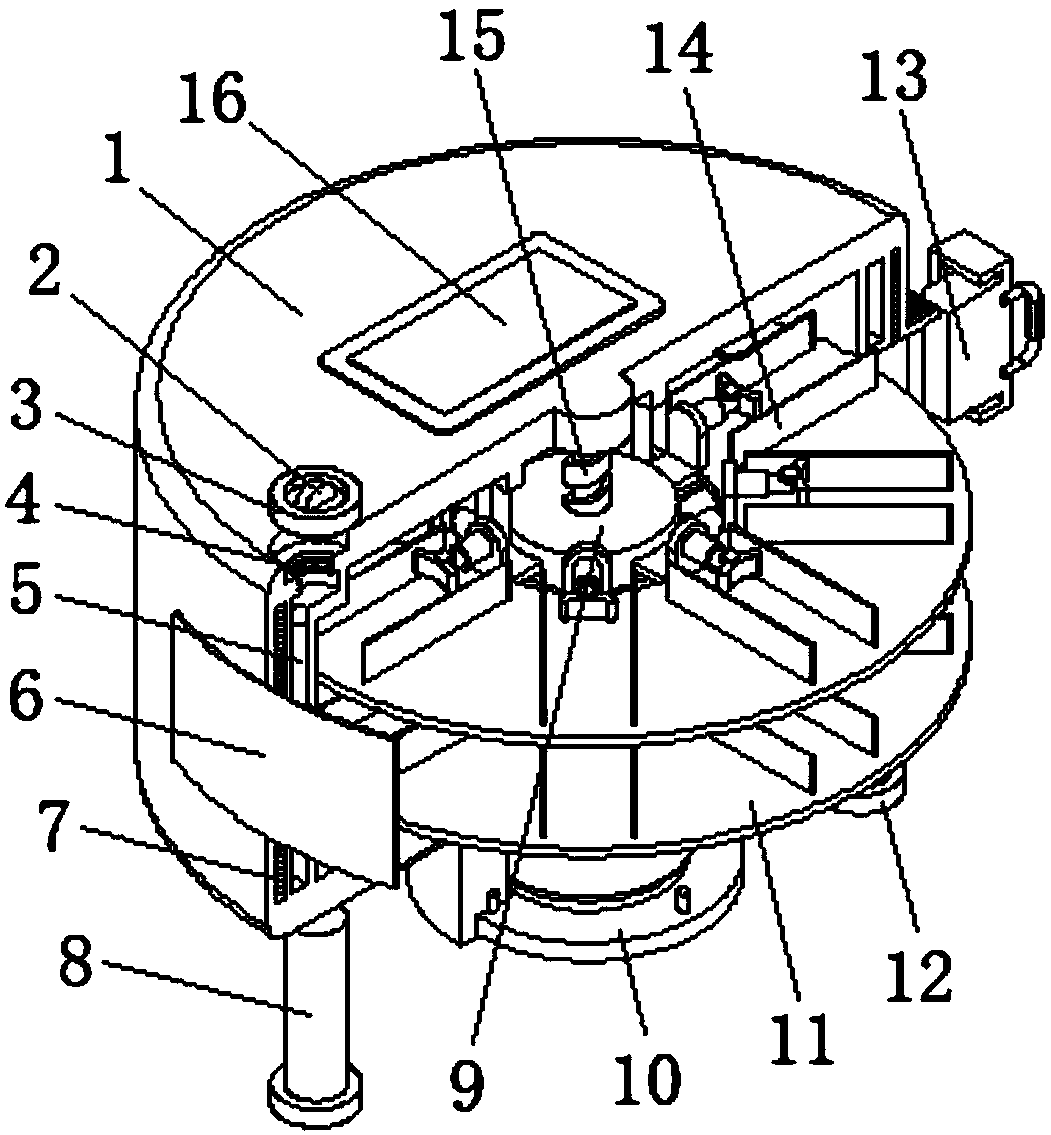
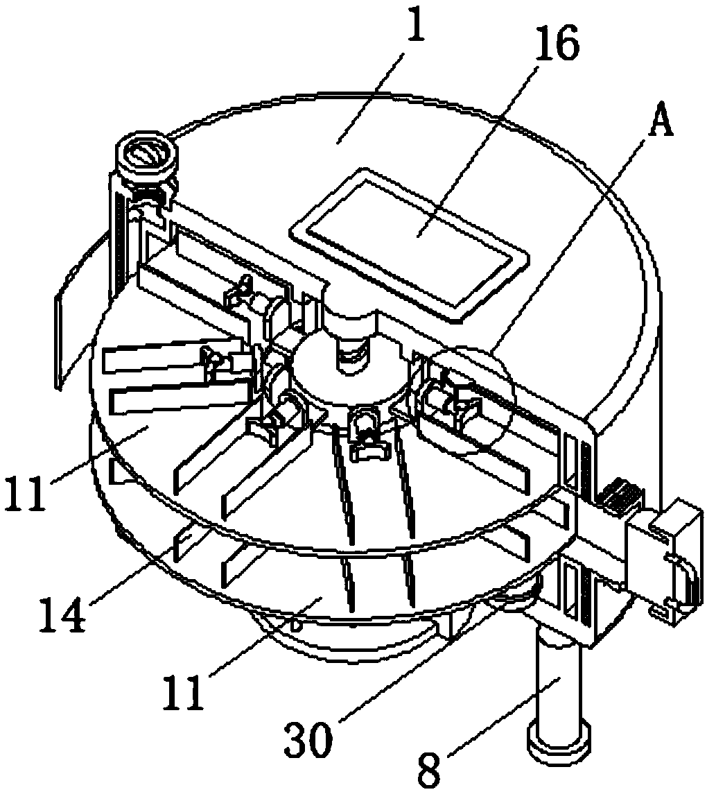
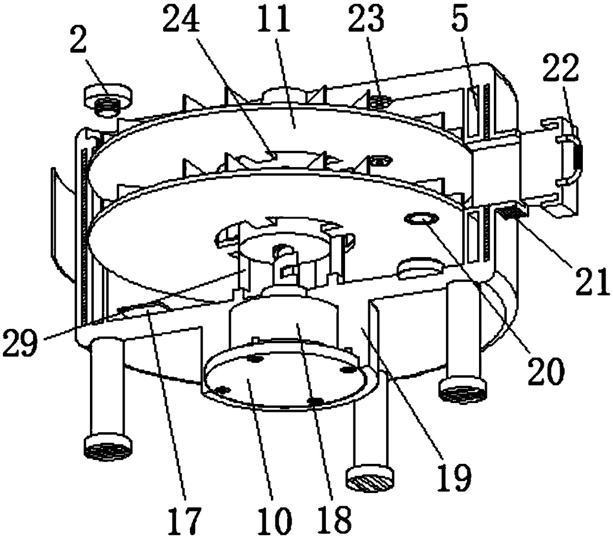
[0025] see Figure 1-4 , the present invention provides a technical solution: a low-temperature storage device for stem cells with high internal space utilization, including a box body 1, an annular heat insulating board 7 is arranged inside the side wall of the box body 1, and the inside of the side wall of the box body 1 is close to the annular One side of the insulation plate 7 is provided with an annular liquid nitrogen storage tank 5, which is used to sto...


PUM


Abstract

The invention discloses a stem cell cryogenic storage device with a high internal space utilization rate. The device comprises a tank. An annular heat insulating plate is arranged in the side wall ofthe tank. One side, close to the annular heat insulating plate, in the side wall of the tank is provided with an annular liquid nitrogen storage tank. One side of the outer part of the tank is provided with a PLC controller. A rectangular discharge groove is arranged in one side wall, far away from the PLC controller, of the tank. A motor box is arranged in the middle of the lower side of the tank. A servo motor is arranged in the middle in the motor box. Through two placement plates in the middle of a screw and partition plates uniformly distributed at the same angle on the upper side of theplacement plates, the inner space utilization rate of the storage device is greatly improved. The annular heat insulating plate is arranged in the side of the tank. Through cooperation of a sealing plunger and a liquid nitrogen feeding hole and cooperation of a rectangular sealing plug and the rectangular discharge groove, the heat insulation effect is improved.

Description

technical field [0001] The invention relates to the technical field of low-temperature storage equipment for stem cells, in particular to a low-temperature storage equipment for stem cells with high internal space utilization. Background technique [0002] Most of the existing low-temperature storage devices are stored in the form of liquid nitrogen tanks. In the field of biomedicine, stem cells can be placed in liquid nitrogen tanks for long-term active storage. When needed, they can be used after thawing and rewarming. The patent No. 201620716173.8 discloses a low-temperature storage device for stem cells. An external rotation system and an adiabatic transmission shaft are installed at the middle of the top of the outer container. The adiabatic transmission shaft is connected to the external rotation system. There is a thermal insulation layer, and a sample rotating tray is installed in the inner tank, and the center of the sample rotating tray is connected with the heat-i...

Claims


Application Information

Patent Timeline
Patent Type & Authority Applications(China)
IPC IPC(8): A01N1/02
CPCA01N1/0257
Inventor 吴文姣
Owner NANHUA UNIV
Why Eureka
Try Eureka