Supercharge Your Innovation With Domain-Expert AI Agents!

Gap diversion type axial-flow pump impeller

A technology for axial flow pumps and slits, which is applied in the field of slit drainage axial flow pump impellers, can solve problems affecting pump efficiency and energy loss, achieve the effect of eliminating wake vortex resistance and improving work efficiency

Inactive Publication Date: 2011-05-18
SHANGHAI UNIV
View PDF6 Cites 6 Cited by
  • Summary
  • Abstract
  • Description
  • Claims
  • Application Information

AI Technical Summary

Problems solved by technology

The flow separation of the boundary layer leads to a large wake vortex resistance, and the wake vortex resistance is often dozens of times the friction resistance of the boundary layer without flow separation, resulting in excessive energy loss and directly affecting the efficiency of the pump

Method used


Image

  • Gap diversion type axial-flow pump impeller
  • Gap diversion type axial-flow pump impeller
  • Gap diversion type axial-flow pump impeller

Examples


Embodiment 1

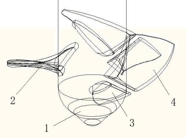
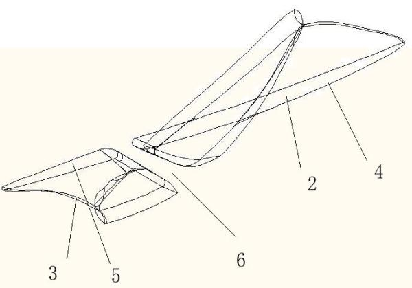
[0019] Embodiment one: see figure 2 and image 3 The impeller of the slit drainage type axial flow pump includes a hub 1 and a blade 2 fixed thereon, and a gap 6 is opened in the middle of the blade so as to divide the blade 2 into a front blade 3 and a rear blade 4 .

Embodiment 2

[0020] Embodiment Two: This embodiment is basically the same as Embodiment One, and the special features are as follows: with reference to the attached figure 2 And attached image 3 , the impeller of the axial flow water pump is composed of a hub 1 and blades 2 fixed on it, wherein the blades 2 are evenly distributed on the hub 1, and the number of blades 2 can be three, four or other numbers, mainly according to the design requirements of the pump to select the number of blades.

[0021] The impeller in this embodiment can be a cast impeller made of grease sand, resin sand or paste gold sand, or a precision cast impeller, or can be a metal processing impeller or a welded impeller. In addition, the idea of ​​this embodiment is not only applied to the impeller of the axial flow water pump, but also applicable to centrifugal or mixed flow impeller blades. Regardless of the type of impeller blade, the opening direction of the gap 6 should conform to the flow direction ...


PUM


Abstract

The invention relates to a gap diversion type axial-flow pump impeller which comprises a hub and a blade fixed on the hub, wherein a gap for diversion is opened on the blade. When fluid passes through the gap, a new boundary layer is produced on the back of the blade, which can bear the reverse pressure gradient of the fluid to effectively eliminate flow separation of the boundary layer, reduce energy loss and ensure relatively high efficiency of the axial-flow water pump under full working conditions.

Description

technical field [0001] The invention relates to a slit drainage type axial flow pump impeller, which belongs to the field of fluid machinery. Background technique [0002] Axial flow pumps have the characteristics of large flow and low head, and are widely used in fields such as water diversion in river basins, farmland irrigation, flood control and drainage, municipal water supply, and water circulation in power plants. Axial flow pump is used. Axial flow pumps have higher efficiency at the design point, but the range of high efficiency is narrow and there is an unstable operation area. During the actual operation of the axial flow pump, it often deviates from the design point, and the boundary layer flow separation is easy to occur on the back of the impeller to form backflow, such as figure 1 shown. The flow separation of the boundary layer leads to a large wake vortex resistance, and the wake vortex resistance is often dozens of times the friction resist...

Claims


Application Information

Patent Timeline
IPC IPC(8): F04D29/18
Inventor 陈红勋魏培茹朱兵张睿
Owner SHANGHAI UNIV
Features
  • R&D
  • Intellectual Property
  • Life Sciences
  • Materials
  • Tech Scout
  • Unparalleled Data Quality
  • Higher Quality Content
  • 60% Fewer Hallucinations
Learn More