
Display panel testing system and microprobe device thereof

A display panel and testing device technology, applied in measuring devices, measuring electricity, measuring electrical variables, etc., to achieve the effects of reducing losses, improving shipment quality, and strengthening market competitiveness

Active Publication Date: 2011-05-18
AU OPTRONICS CORP
View PDF6 Cites 1 Cited by
  • Summary
  • Abstract
  • Description
  • Claims
  • Application Information

AI Technical Summary

Problems solved by technology

The test device is used to generate test signals

Method used


Image

  • Display panel testing system and microprobe device thereof
  • Display panel testing system and microprobe device thereof
  • Display panel testing system and microprobe device thereof

Examples


Embodiment Construction

[0039] A specific embodiment according to the present invention is a display panel testing system. In this embodiment, the display panel testing system is used to test the display panel to be tested. In fact, the display panel to be tested is preferably a liquid crystal display panel, but not limited thereto. In addition, the size of the display panel to be tested and the circuit spacing of its integrated circuits can also be determined according to actual needs, and there is no specific limitation.

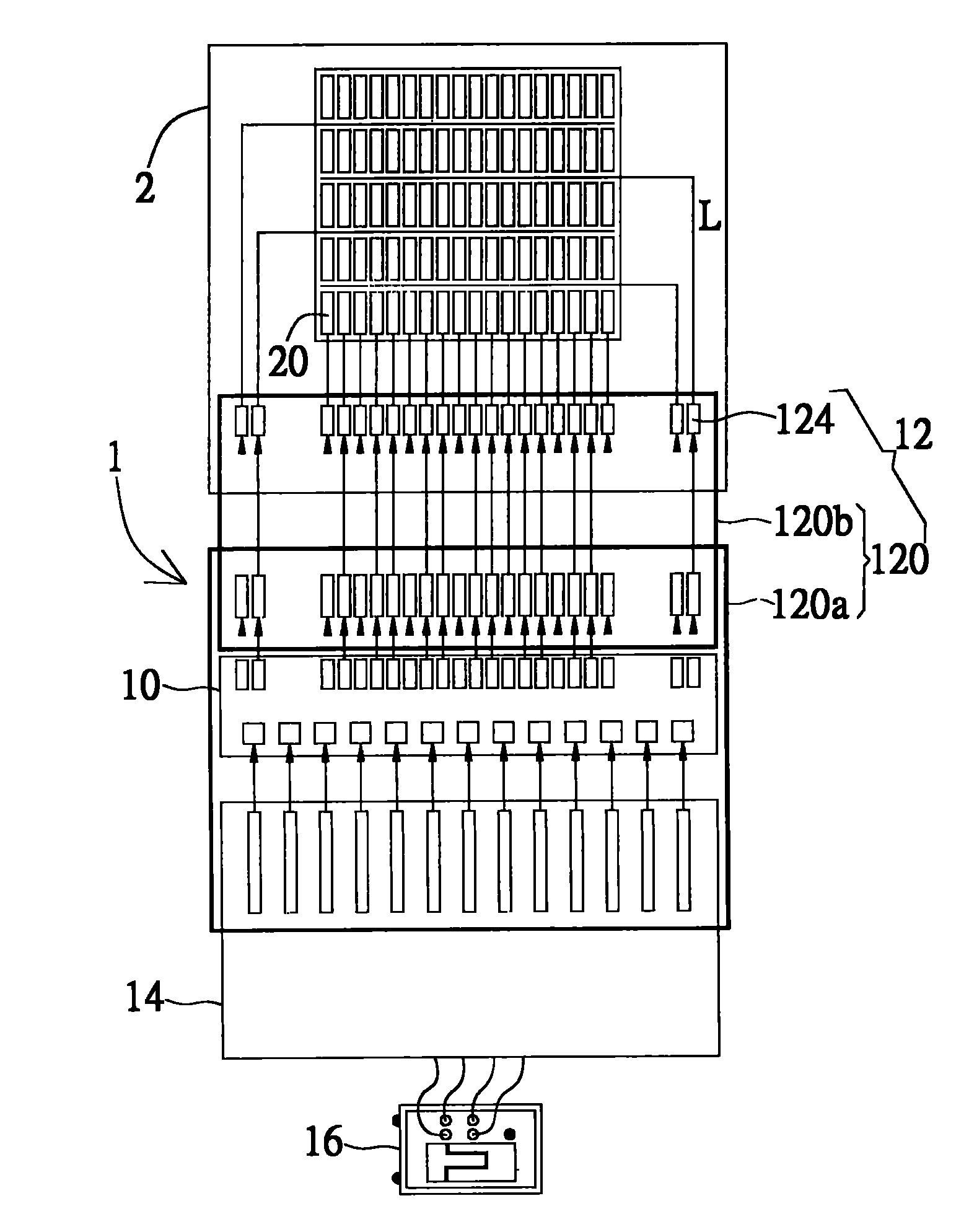
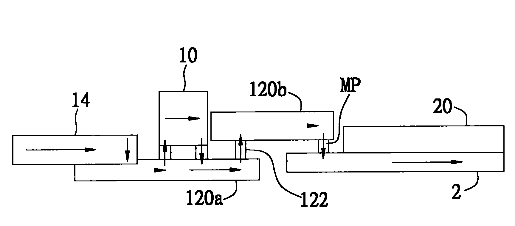
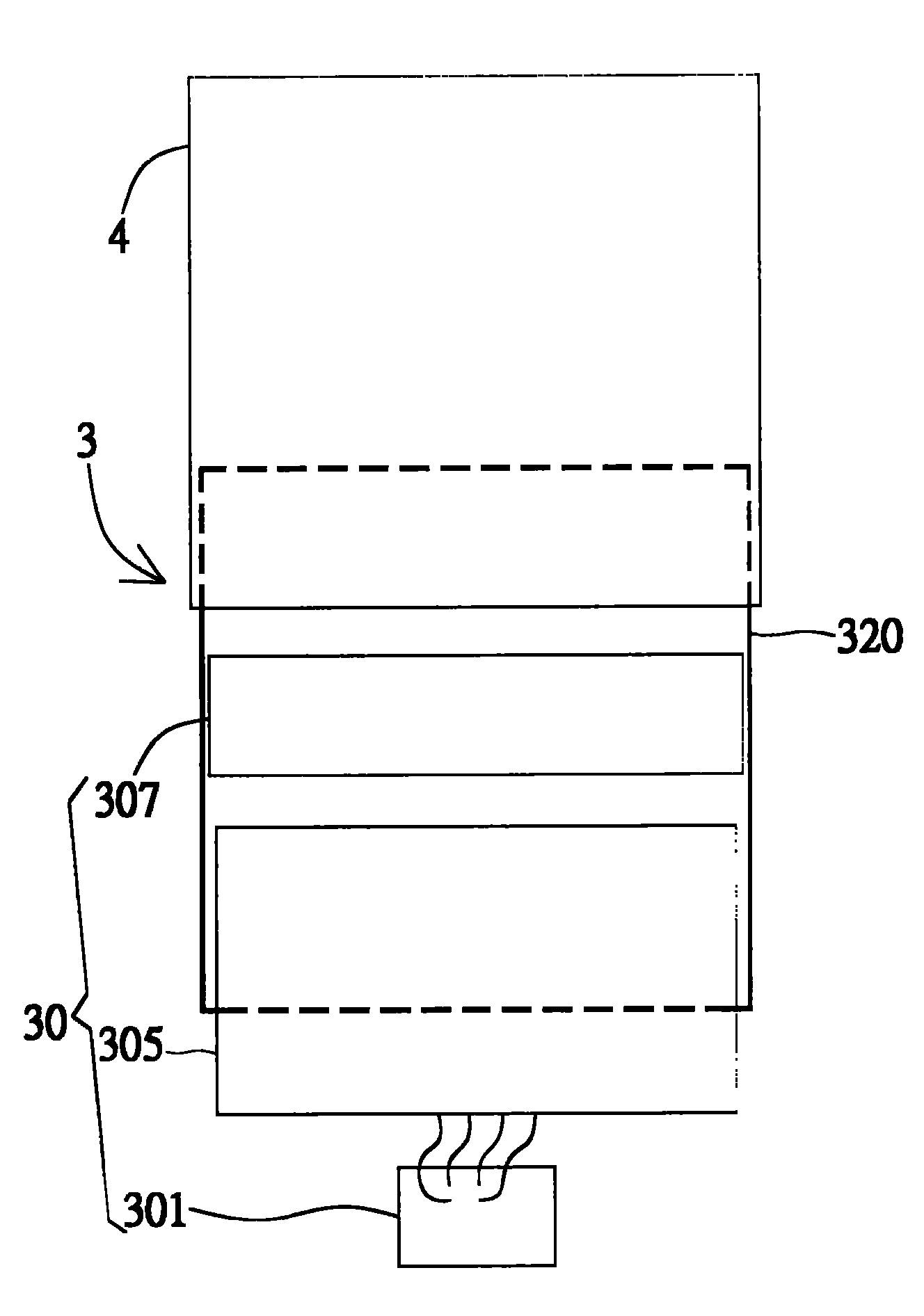
[0040] Please refer to Figure 3A and Figure 3B , Figure 3A and Figure 3B It is a schematic diagram showing the appearance and structure of the display panel testing system respectively. As shown in the figure, the display panel testing system 3 includes a testing device 30 and a micro-probe device 32 for testing signal lines and pixels of the display panel 4 to be tested. In this embodiment, the test device 30 includes a test signal generator 301 , a circuit board modul...


PUM


Abstract

The invention discloses a display panel testing system comprising a testing device and a microprobe device which are used for testing a display panel to be tested. The testing device is used for generating testing signals; the microprobe device comprises a substrate and a microprobe; the substrate is coupled with the testing device and provided with testing integrated circuits arranged symmetrically; and the microprobe is arranged on the substrate and coupled with the display panel to be tested. When being inputted into the substrate of the microprobe device and transmitted to the testing integrated circuits along a specific path, the testing signals are reversed by the testing integrated circuits and transmitted to the substrate of the microprobe device, and then the testing signals are outputted to the display panel to be tested through the microprobe.

Description

technical field [0001] The present invention is related to display panels, in particular to a micro-probe device with a monolithic substrate structure and a display panel testing system using the micro-probe device. Background technique [0002] Currently, there are various types of flat panel display devices (FPD) on the market, such as liquid crystal display devices (LCD), organic electroluminescent display devices (OLED) and plasma display devices (PDP). However, no matter what kind of flat-panel display device it is, it is necessary to test its signal lines (such as scan lines and data lines) and pixels during the manufacture of its display panel, so as to determine the flat panel produced. The display device is functioning normally. [0003] Generally speaking, the test methods of signal lines and pixels on the display panel can be roughly divided into two types: full contact probe test method and shorting bar probe test method. In the early days, the shorting bar pro...

Claims


Application Information

Patent Timeline
Patent Type & Authority Applications(China)
IPC IPC(8): G01R1/067G01R31/00
Inventor 邓国鑫邵明良吴坤育陈执群陈文钧蔡孟哲陈建利苏裕新
Owner AU OPTRONICS CORP
Learn More