Method for implementing light spot joint seal in fiber densely-arranged line array and module

A technology of optical fiber module and line array, which is applied in the field of optical fiber close-packed scanning imaging, which can solve the problems of large width of close-packed array, complex control circuit, and high requirements for focusing imaging optical system

Inactive Publication Date: 2011-05-18
HANGZHOU SUONA TECH
View PDF12 Cites 11 Cited by
  • Summary
  • Abstract
  • Description
  • Claims
  • Application Information

AI Technical Summary

Problems solved by technology

This method is successful, but the control circuit is very complicated. When more optical fibers are arranged (128, 256 or 512)

Method used


Image

  • Method for implementing light spot joint seal in fiber densely-arranged line array and module
  • Method for implementing light spot joint seal in fiber densely-arranged line array and module
  • Method for implementing light spot joint seal in fiber densely-arranged line array and module

Examples


Embodiment 1

[0031] (Using a single-sided V-groove substrate to make a 128-way double-layer staggered optical fiber close-packed array)

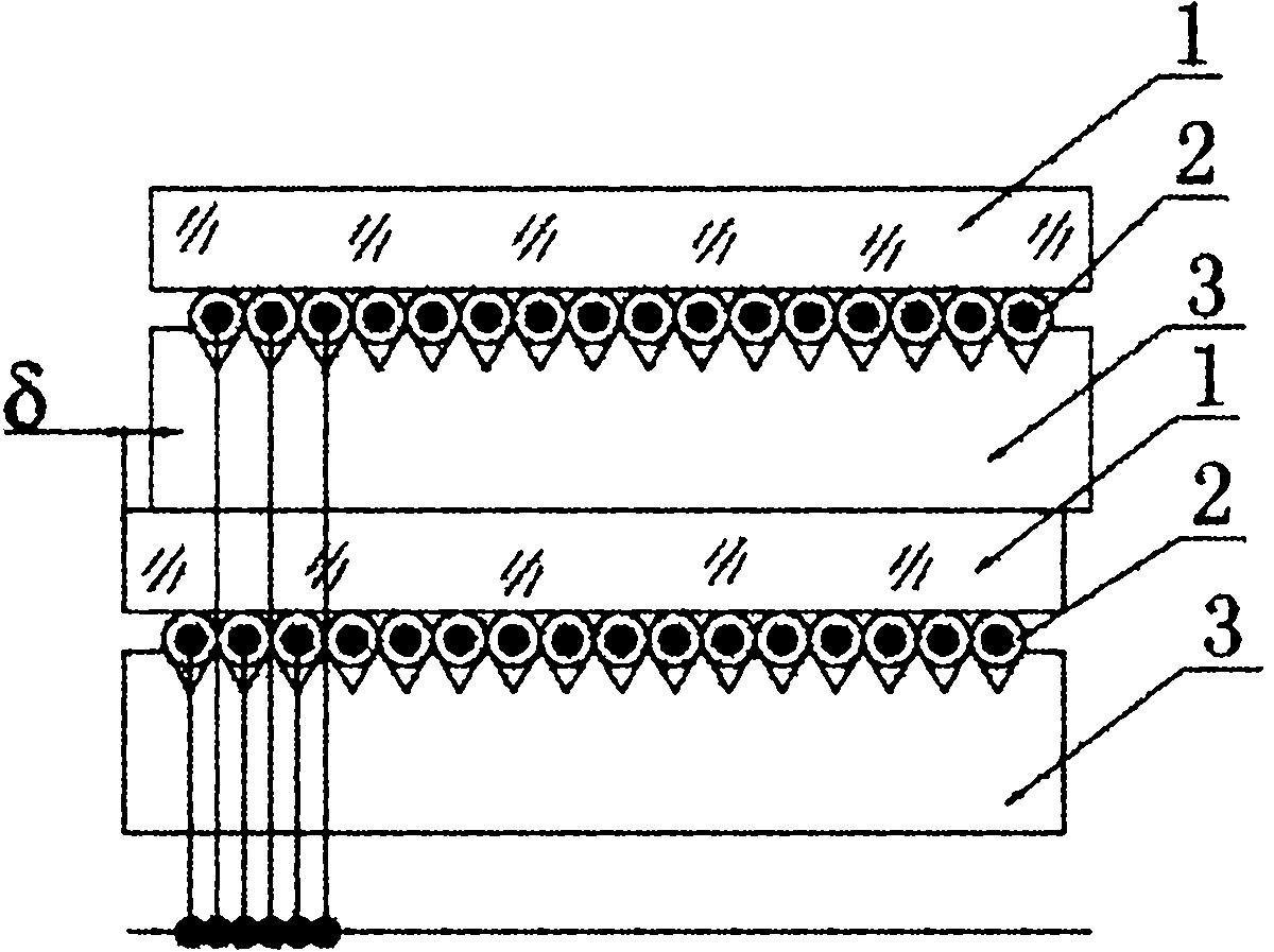
[0032]Using standard 62.5 / 125 multimode optical fiber, arrange the optical fiber in the V-shaped groove of the substrate (silicon substrate or organic polymer substrate) with equally spaced V-shaped grooves on one side, drip UV glue, cover The upper glass plate is irradiated with ultraviolet light to cure it, and a module with 64 optical fibers is produced. Using the same process, the same 64-channel optical fiber close-packed module was fabricated. Stack the two 64-channel optical fiber close-packed modules up and down, and precisely control the position of the two modules in the direction of the fiber array, so that the corresponding optical fibers of the two modules are staggered by a distance of 62.5 microns, and then use ultraviolet glue to glue the two modules together. Solidified as a whole, thus a double-layer optical fiber close-packed array wi...

Embodiment 2

[0036] (Using double-sided V-groove substrates to fabricate 128-way double-layer staggered optical fiber close-packed arrays)

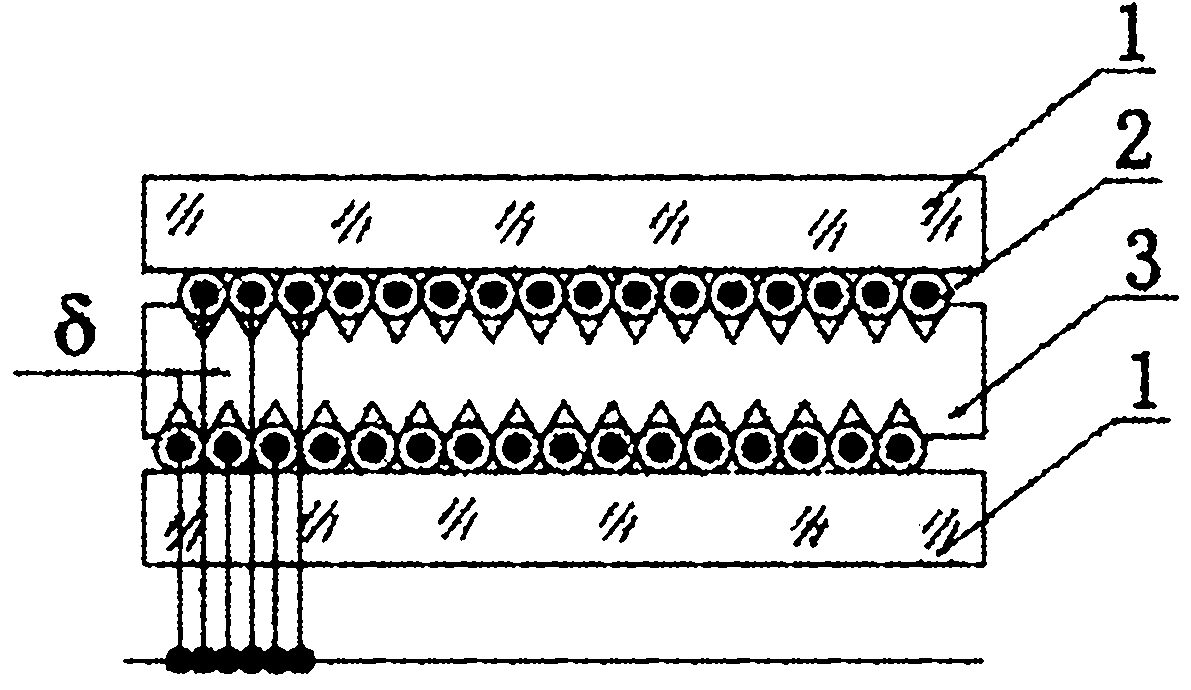
[0037] Make a substrate (silicon substrate or organic polymer substrate) with V-shaped grooves distributed at equal intervals on both sides, so that the V-shaped grooves on both sides are staggered left and right by 62.5 microns in the vertical direction, using the standard 62.5 / 125 more Mode optical fiber, operate on the two surfaces of the substrate respectively, first place the optical fiber on the V-groove position on one of the surfaces, drip UV glue, cover the glass platen, irradiate it with UV light to cure it, repeat the above process, complete the operation on the other side, that is, a module with 128 double-layer optical fibers densely packed can be produced, such as image 3 As shown, 1 is the glass plate, 2 is the standard 62.5 / 125 multimode fiber, 3 is the substrate, and δ is the distance between the two layers of optical fiber.

Embodiment 3

[0039] (Using a single-sided V-groove substrate to make a 256-way four-layer staggered optical fiber close-packed array)

[0040] Using 30 / 125 multimode optical fiber, arrange the optical fiber on the substrate (silicon substrate or organic polymer substrate) with V-shaped grooves distributed at equal intervals on one side, drip UV glue, cover the glass plate, and use It is cured by ultraviolet light irradiation, and a module with 64 optical fibers is produced. Using the same process, three identical optical fiber close-packed modules with 64 channels were fabricated. Stack the four 64-channel optical fiber close-packed modules up and down, and precisely control the positions of the four modules in the direction of the fiber array, so that the corresponding optical fibers of adjacent modules are sequentially staggered by a distance of 31.25 microns, and then glue the four modules together with ultraviolet glue. The module is solidified into a whole, so that a four-layer optic...


PUM


Abstract

The invention discloses a method for implementing alight spot joint seal in a fiber densely-arranged line array, which comprises the following steps of: (1) taking a substrate graved with a plurality of grooves distributed in equal spacing distance on the surface; putting fibers in the grooves of the substrate respectively, and fixing the fibers and the substrate to obtain a densely-arranged fiber layer assembly; and (2) preparing a plurality of densely-arranged fiber layer assemblies with the same method as the step (1), and stacking the prepared fiber layer assemblies together in parallel up and down, wherein the fibers on the upper and lower fiber layers are staggered to ensure the projection light spots of all fiber array output light spots in a densely-arranged fiber module on a horizontal line are in joint seal or proper superposed arrangement. The invention also discloses a densely-arranged fiber module prepared with the method. The densely-arranged fiber module avoids the problems of poor output image quality and over high requirement for a focusing and imaging lens because more fibers are arranged in single-layer fiber arrangement, the arranged fiber array is widened and the lead angle is largened in spiral scanning and imaging.

Description

technical field [0001] The invention belongs to the technical field of optical fiber close-arrangement scanning imaging, and specifically relates to a method for realizing close connection of light spots in an optical fiber densely-arranged line array in laser phototypesetting, printing imaging, laser photopainting and direct plate-making systems, and the realization obtained by the method A close-packed optical fiber module in which light spots are closely connected in an optical fiber close-packed line array. Background technique [0002] In laser scanning equipment such as laser phototypesetting machines, printing imaging machines, laser photoplotters, and direct plate-making machines, a main solution to realize multi-channel optical scanning is to use multiple semiconductor lasers and multiple optical fibers to construct a light source. The dot line array is used as the object plane, and is then imaged on the image plane (film or exposure plate surface) in a certain prop...

Claims


Application Information

Patent Timeline
IPC IPC(8): G02B6/36G02B6/00B41B19/00
Inventor 侯昌伦
Owner HANGZHOU SUONA TECH
Why Eureka
Try Eureka