Linear light beam reshaper

A technology of beam shaping and shaper, which is applied in lasers, laser components, optics, etc., can solve the problems of increasing the difficulty of processing and side coating, the inability to adjust the distance of split beams, and increasing beam loss, etc., to achieve easy processing and easy installation , Improve the effect of brightness

Inactive Publication Date: 2005-10-19
TSINGHUA UNIV
View PDF2 Cites 0 Cited by
  • Summary
  • Abstract
  • Description
  • Claims
  • Application Information

AI Technical Summary

Problems solved by technology

This shaping method overcomes the shortcomings of the reflection loss of the "ladder mirror" method because of total internal reflection, but the beam is split through the thickness of the prism, and the beam splitting is limited by the thickness of the prism, which limits the further improvement of the brightness of the shaped beam, and usually prism processing The thickness should be more than 0.7mm. The thinner the prism, the difficulty of processing and side coating will be greatly increased, and the beam loss will also be increased.
The arrangement distance of the split beams is also limited by the thickness of the prism, and the distance between the split beams cannot be adjusted

Method used


Image

  • Linear light beam reshaper
  • Linear light beam reshaper
  • Linear light beam reshaper

Examples


Embodiment 1

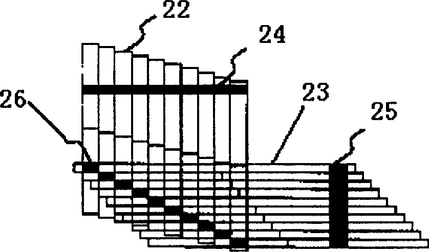
[0028] like Figure 10 The shaper shown by Figure 9 The prisms shown are misaligned and closely packed. Assume that the length of the linear beam after collimation on the fast axis is D=12mm, and the divergence angle of the slow axis is θ s =10°, fast axis divergence angle θ f =0.5°, take N = θ s θ f = 20 , Then the misalignment distance between the prisms is 12 20 = 0.6 mm , The outgoing beam must meet the same Lagrange quantity in the two directions to achieve the effect of shaping D / N×θ s =N×d×θ f , d=0.6mm can be obtained, then the optical path difference Δd=0 of the light beam between the first reflective surface and the second reflective surface of each prism, and the requirement of beam shaping can be achieved by making each pri...

Embodiment 2

[0030] Assuming that the light source to be shaped is a diode array composed of two diodes, the beams collimated by the fast axis are two parallel linear beams, the length of each linear beam is D=12mm, and the divergence angle of the slow axis is θ s =10°, fast axis divergence angle θ f =0.5°, suppose the linear light beam interval is 0.3mm, the same as example 1, the misalignment distance of the prism is 0.6mm,

[0031] The obtained Lagrange quantities of the reshaped beam in two directions are the same as those in Example 1, because the power of the two beams is doubled, and the brightness of the reshaped beam is also doubled.


PUM


Abstract

The invention is a linear light beam shaper, belonging to optical component field. It is composed of above two mircoprisms dislocated and closely arranged, each microprism has three all-reflecting surfaces, N microprisms change the light beam into N vertical closely-arranged light beam groups, the distance between the light beam groups can be controlled by the difference of optical distance of the light beam between the first and second reflecting surfaces of the two adjacent microprisms and after shaped, the light beam does not change the advancing direction. It has compact structure, convenient processing and film plating, simple and convenient to install and clamp and high shaping efficiency, and other characters.

Description

technical field [0001] The invention relates to a linear beam shaper composed of transmission elements. It is mainly used in the beam shaping of linear light-emitting devices of semiconductor lasers, and improves the focusing and coupling performance of the beam by changing the shape and spatial distribution of the beam, and belongs to the field of optical components. Background technique [0002] With the development of semiconductor integration and assembly technology, the power of semiconductor lasers has been greatly improved in recent years. High-power semiconductor lasers have two main uses: one is directly used as a laser source, such as in beauty, medical treatment 1. Applications in material processing; 2. Pumping solid-state lasers or fiber lasers as pump sources to replace lamp-pumped solid-state lasers, which have been widely used in industrial processing, material processing, medical beauty and military industries. Since the semiconductor laser has an extremely...

Claims


Application Information

Patent Timeline
Patent Type & Authority Patents(China)
IPC IPC(8): G02B5/04G02B27/09H01S3/00
Inventor 巩马理肖力敏闫平欧攀
Owner TSINGHUA UNIV
Why Eureka
Try Eureka