Motor, disc drive device, rotor yoke manufacturing method and motor manufacturing method

A manufacturing method and motor technology, applied in the field of motors, can solve problems such as rising manufacturing costs, rotor yoke burrs, and burr shedding

Inactive Publication Date: 2011-05-18
NIDEC CORP
View PDF10 Cites 5 Cited by
  • Summary
  • Abstract
  • Description
  • Claims
  • Application Information

AI Technical Summary

Problems solved by technology

However, if the amount of press-fit interference is increased, burrs (useless protrusions) are likely to be generated at the end of the rotor yoke
If a burr is generated, the burr will fal

Method used


Image

  • Motor, disc drive device, rotor yoke manufacturing method and motor manufacturing method
  • Motor, disc drive device, rotor yoke manufacturing method and motor manufacturing method
  • Motor, disc drive device, rotor yoke manufacturing method and motor manufacturing method

Examples


Embodiment Construction

[0028] Hereinafter, exemplary embodiments of the present invention will be described with reference to the drawings. Hereinafter, the direction along the central axis of the motor is referred to as the up-down direction, and the side of the rotating part relative to the stationary part is referred to as up, and the shape and positional relationship of each part will be described. However, this is merely a definition of the vertical direction for convenience of description, and the installation posture of the motor and the disk drive device according to the present invention when mounted in an actual device is not limited to this.

[0029]

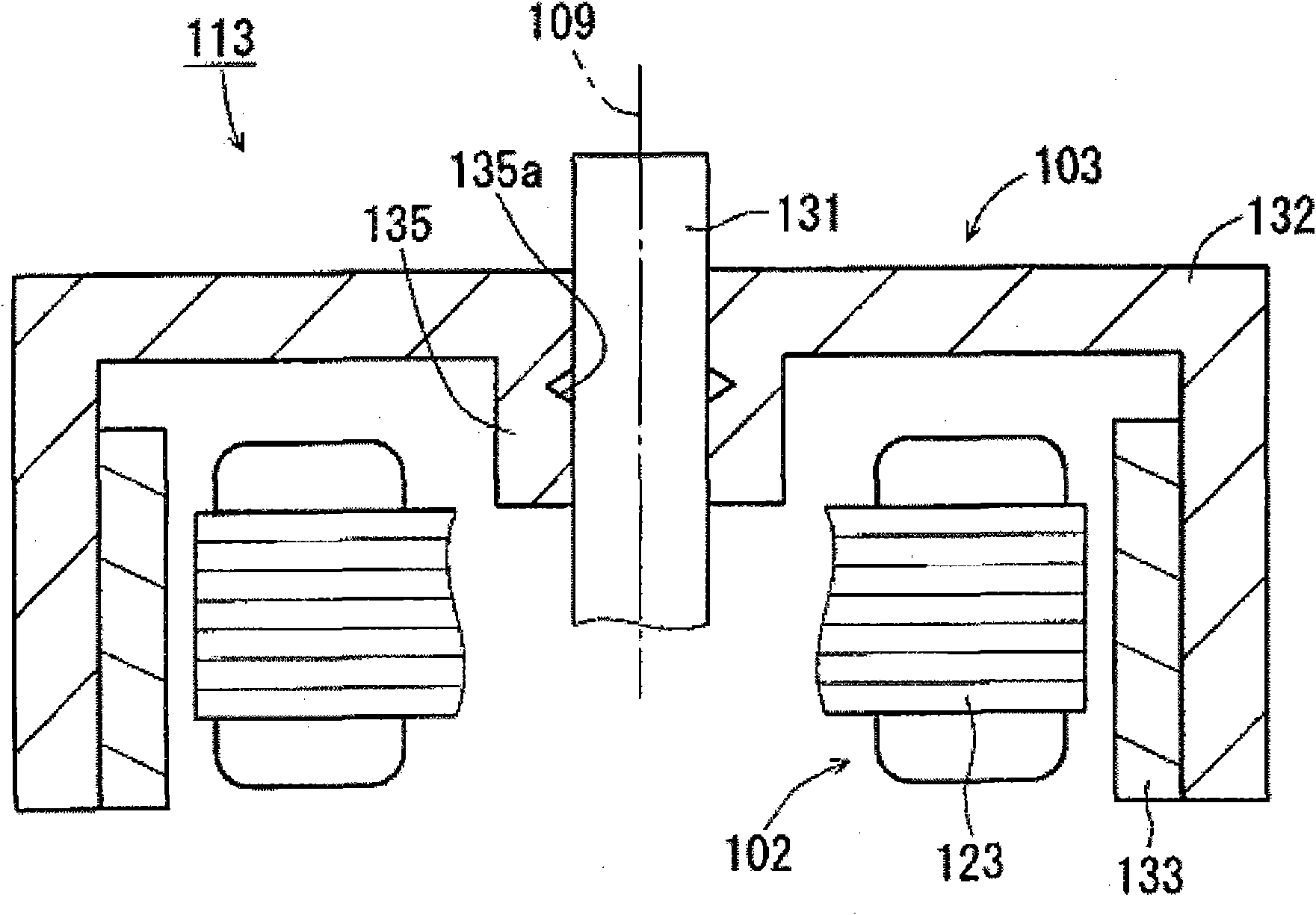
[0030] figure 1 It is a vertical cross-sectional view of the motor 113 according to one embodiment of the present invention. Such as figure 1 As shown, the motor 113 includes a stationary part 102 and a rotating part 103 . The rotating part 103 is supported by the stationary part 102 via a bearing part (not shown) in a rotatable state ...


PUM


Abstract

The invention provides a motor, a disc drive device, a rotor yoke manufacturing method and a motor manufacturing method. The motor has a stationary portion and a rotating portion which, in a state of being capable of rotating with a central shaft extending up and down as the center, is supported by the stationary portion. The stationary portion has a stator which generates magnetic flux. The rotating portion is provided with a shaft configured along the central shaft, a rotor yoke which has a cylindrical fastened portion fastened to the shaft by pressing, and a rotor magnet which is fixed to the rotor yoke and is opposite to the stator in the radial direction. The shaft has a portion extruding up and down from the fastened portion. In addition, the inner circumferential surface of the fastened portion forms a concave portion. When the shaft is pressed into the fastened portion of the rotor yoke, flash which is generated because the inner circumferential surface of the fastened portion is stroked is received in the concave portion, so that the generation of axial end flash of the fastened portion is restrained. Moreover, in this way, due to no use of adhesives, the press-in interference is increased, and the shaft and the rotor yoke can be firmly fastened.

Description

technical field [0001] The present invention relates to an electric motor, a disk drive device, a method for manufacturing a rotor yoke, and a method for manufacturing an electric motor. Background technique [0002] A disk drive device such as an optical disk drive is equipped with a brushless motor for rotating the disk. As an example of such a brushless motor, US Pat. No. 6,534,889 describes a motor in which a rotating shaft and a rotating body are fixed. Also, US Pat. No. 6,700,256 describes a brushless motor including a substantially cylindrical rotor frame and a shaft whose one end is fixed to the rotation center of the rotor frame. [0003] [Patent Document 1] Specification of US Patent No. 6,534,889 [0004] [Patent Document 2] Specification of US Patent No. 6,700,256 [0005] In US Pat. No. 6,534,889, after press-fitting and fixing the rotating body and the rotating shaft, they are bonded and fixed with an adhesive. In addition, in US Pat. No. 6,700,256, the sha...

Claims


Application Information

Patent Timeline
IPC IPC(8): H02K1/28H02K15/03H02K15/00G11B17/022
Inventor 纲岛大辅林重雄
Owner NIDEC CORP
Why Eureka
Try Eureka