Method for the operative monitoring of track brakes

A track brake and operation monitoring technology, applied in the direction of brakes, brake components and track interaction brakes, brake components, etc., can solve the problem of inaccurate and wrong signals of sensors

Active Publication Date: 2011-05-18
KNORR BREMSE SYST FUR SCHIENENFAHRZEUGE GMBH
View PDF5 Cites 8 Cited by
  • Summary
  • Abstract
  • Description
  • Claims
  • Application Information

AI Technical Summary

Problems solved by technology

[0009] However, the sensors cause additional costs and there is the risk that, in the event of functional defects or failures of the sensors, errors are not detected or inaccurate error signals are generated

Method used


Image

  • Method for the operative monitoring of track brakes
  • Method for the operative monitoring of track brakes
  • Method for the operative monitoring of track brakes

Examples


Embodiment Construction

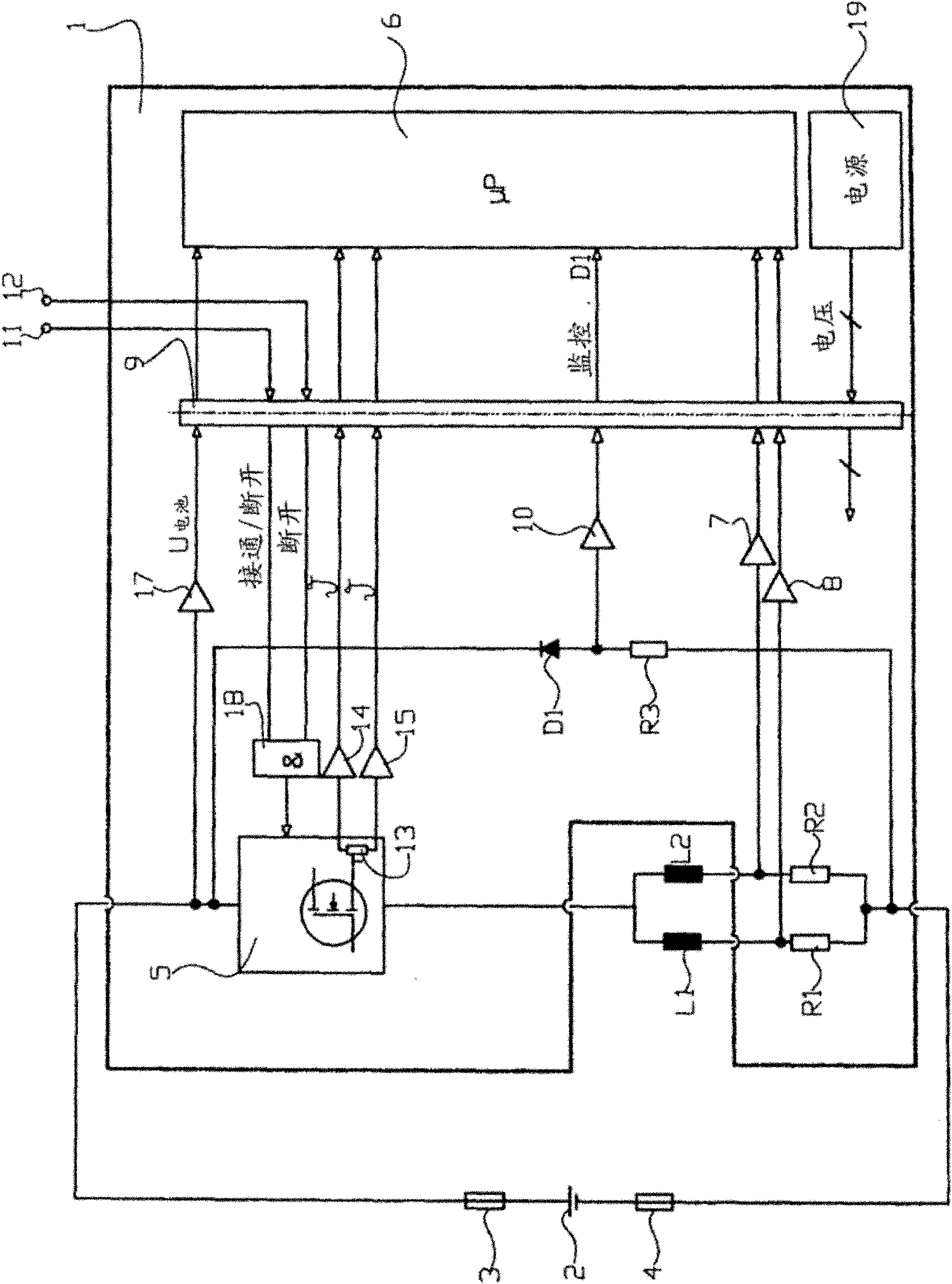
[0024] figure 1 A control device 1 is shown for controlling the braking electromagnets, which are represented as inductances L1 and L2 in the figure 1 circuit diagram.

[0025] The control device 1 is supplied with electrical energy from the vehicle electrical system, for example a battery 2 , the control device being connected to the poles of the battery via a fuse 3 or 4 .

[0026] The two inductors L1 and L2 are in a circuit comprising a power switch 5 controlled by a microprocessor 6 and the inductors L1 and L2 are connected to the battery voltage of the battery 2 . Two inductors L1 and L2 are connected in series with shunt resistors R1 or R2 respectively, and the voltage drop of these shunt resistors is proportional to the current flowing through the inductors L1 or L2. The voltage is tapped at a common connection point between inductances L1 and L2 and shunt resistors R1 and R2 and passed on to microprocessor 6 via measuring amplifier 7 or 8 . The microprocessor 6 is ...


PUM


Abstract

The invention for the operative monitoring of track brakes, according to which an electric current passes through a winding of a brake magnet, measures the electric current (i2, i4) and compares the temporal progression of the measured current (i2, i4) with a saved temporal progression of a reference current (i1, i3). In particular, the comparison is achieved by claculating the difference between the measured current and the reference current. Preferably, the difference between the measured current and the reference current is temporally integrated and compared with a threshold value. To determine a magnetic coupling between the track brake and the track, a calculation is made as to whether the measured current has local minima (e min) and/or local maxima (e max) during the activation of the track brake, only the temporal progression of the measured current as said current increases being subjected to a comparison with the reference current. The current is preferably activated in pulses, with the comparison of the measured current and the reference current being restarted with each pulse.

Description

technical field [0001] The invention relates to a method for operating a rail brake for monitoring rail vehicles according to the preamble of claim 1 . Background technique [0002] Such a method is known from DE 101 55 143 A1. [0003] Modern rail vehicles are often equipped with magnetic rail brakes, which are designed as eddy current brakes or magnetic rail brakes, in addition to pneumatic brakes. [0004] "High suspension" is common in railway mainlines, where the brake electromagnet is held by a spring at a predetermined height of about 100mm above the track. For the braking process, the spring force is overcome by the pneumatically actuated cylinder and the brake solenoid is lowered from its upper position into its operating position on the rail. At the same time, electricity is applied to the brakes (cf. Wolfgang Hendrichs: "Das statische, dynamische und thermische Verhalten von Magnetschienen-bremsen", Elektrische Bahnen eb, 86. Annual, Issue 7 / 1988, pp. 224-228). ...

Claims


Application Information

Patent Timeline
Patent Type & Authority Applications(China)
IPC IPC(8): B60T17/22B61H7/08
CPCB61H7/08B60T17/228
Inventor H·莱曼J·达茨雷特尔F·达克塞克尔P·施拉格
Owner KNORR BREMSE SYST FUR SCHIENENFAHRZEUGE GMBH
Why Eureka
Try Eureka