Titanium oxide coated carbon fiber and porous titanium oxide coated carbon material composition

A technology of titanium oxide and carbon materials, applied in the direction of carbon fibers, carbon compounds, fibrous fillers, etc., can solve the problems of increased leakage current and reduced power generation efficiency

Inactive Publication Date: 2011-05-18
OSAKA GAS CO LTD
View PDF5 Cites 14 Cited by
  • Summary
  • Abstract
  • Description
  • Claims
  • Application Information

AI Technical Summary

Problems solved by technology

However, if the carbon nanotubes are not sufficiently coated with the active material oxide, the leakage current increases, causing a problem of lower power generation efficiency

Method used


Image

  • Titanium oxide coated carbon fiber and porous titanium oxide coated carbon material composition
  • Titanium oxide coated carbon fiber and porous titanium oxide coated carbon material composition
  • Titanium oxide coated carbon fiber and porous titanium oxide coated carbon material composition

Examples


Embodiment 1

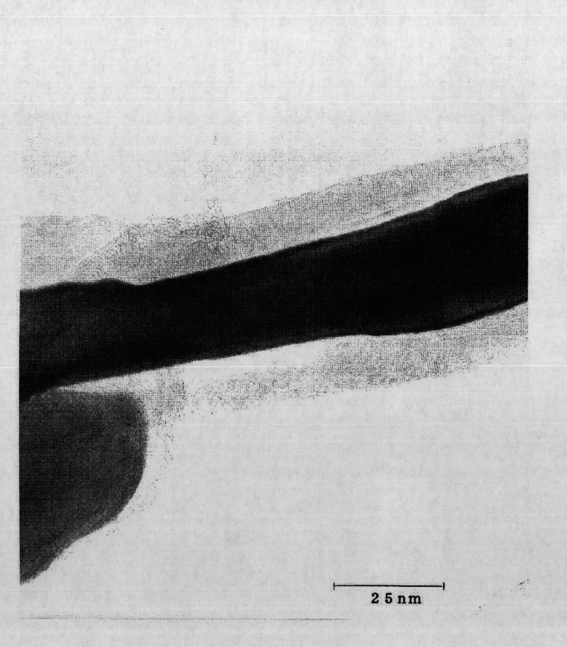
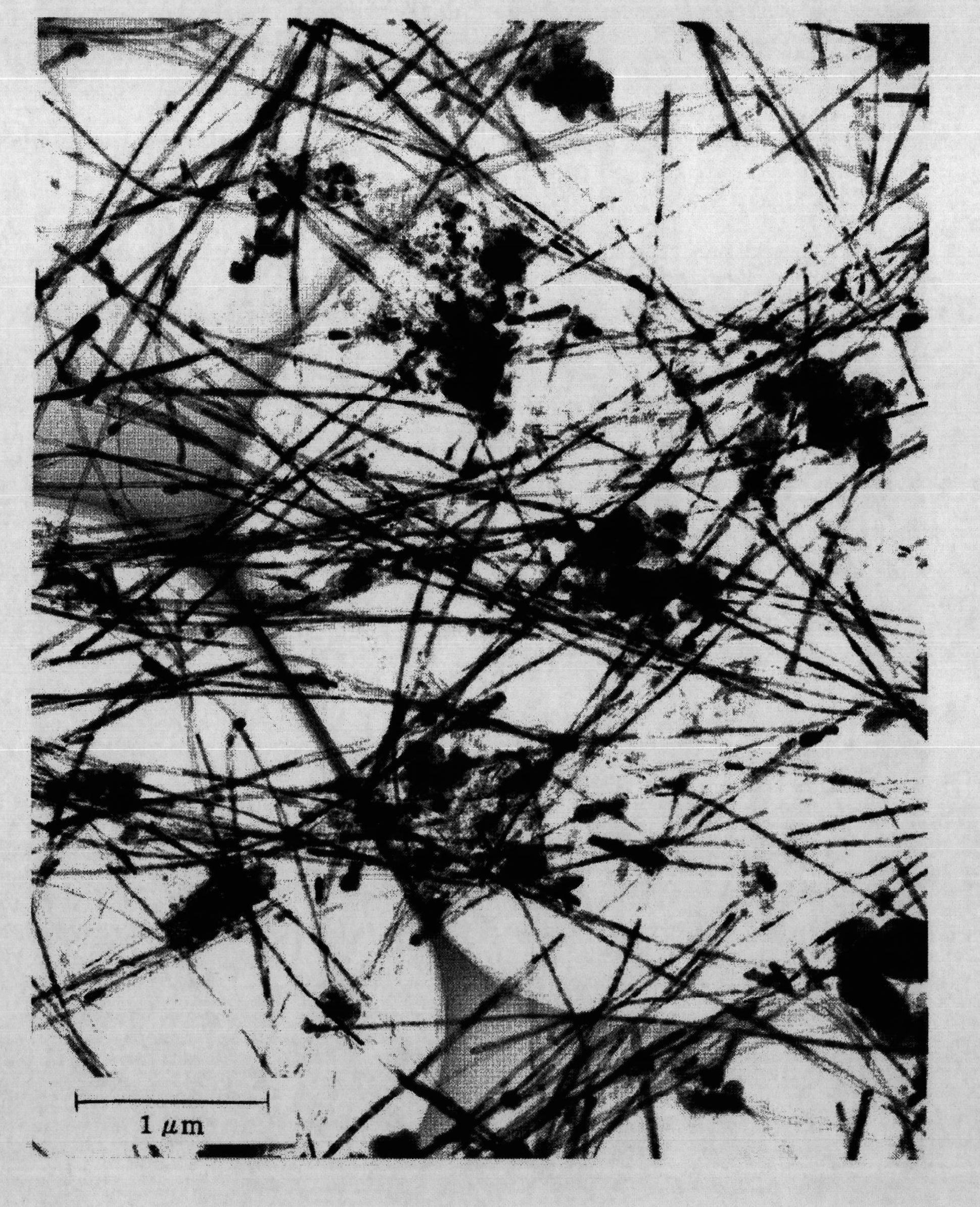
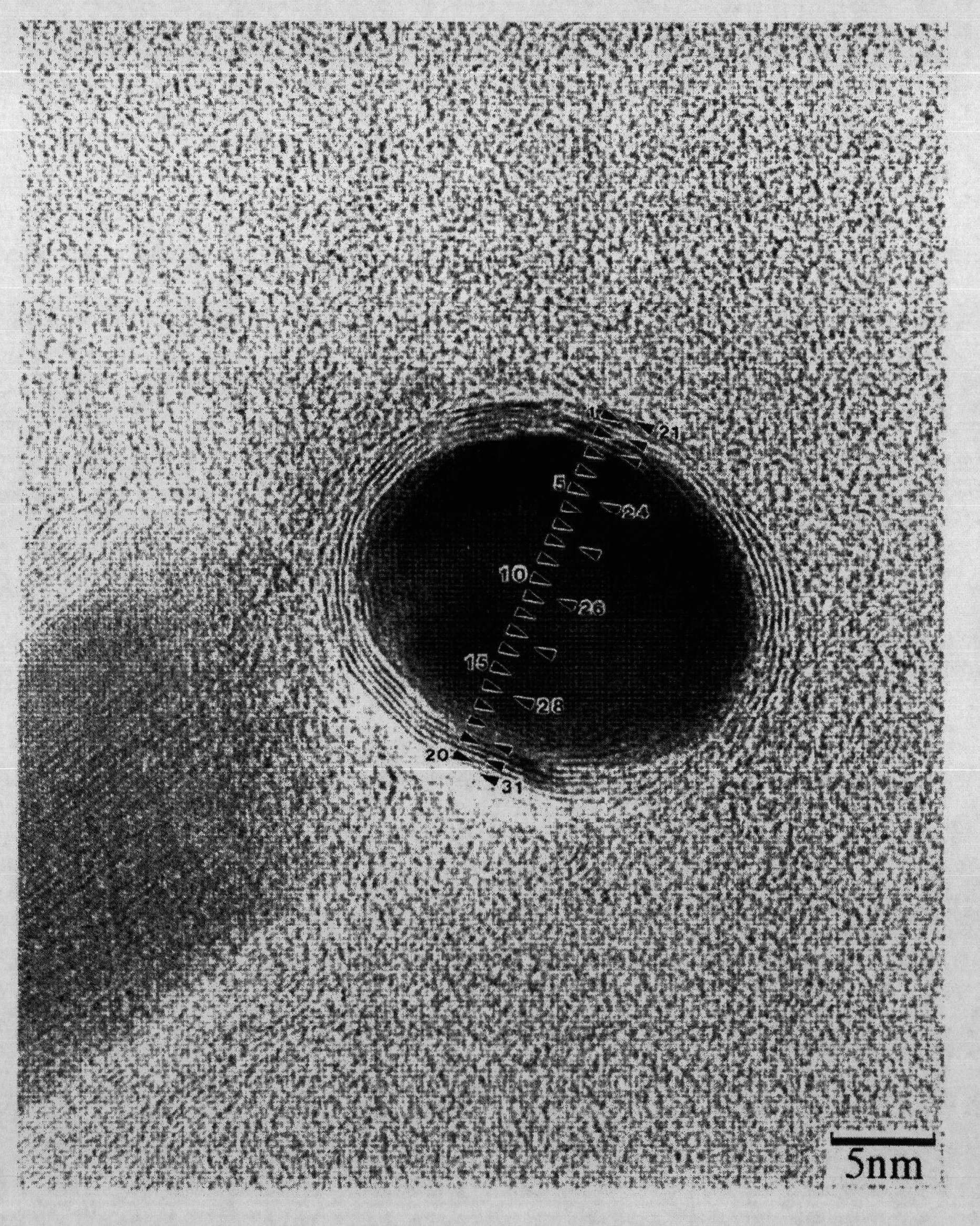
[0231] 150 g of 69% nitric acid was added to 0.96 g of carbon nanotubes (average diameter: 35 nm, average length: 5,000 nm, average aspect ratio: 143), and the mixture was maintained at 90˜95° C. for 6 hours. The resulting material was filtered, washed with distilled water until the filtrate showed a pH of 6-7, and dried.

[0232] The dried product was dispersed in 100 g of distilled water containing 3.7 g of polyether dispersant using an ultrasonic homogenizer. Ammonium hexafluorotitanate diluted to 1.0M and boric acid diluted to 1.0M were added to the nanoscale carbon dispersion at concentrations of 0.20M and 0.4M, respectively. The mixture was allowed to stand at 35° C. for 16 hours, followed by filtration and drying to obtain a structure in which the surface of the nanoscale carbon tubes was coated with titanium oxide (nanoscale carbon coated with titanium oxide Tube).

[0233] According to TG / DTA measurement, carbon nanotubes burn violently around 550°C, while the prepa...

experiment example 1-1

[0240] The structure before firing produced in Example 1 was processed into a 0.3 mm thick flat plate under a pressure of 10 MPa, and a voltage of 1 V was applied between the sheets. As a result, it was confirmed that the current value was 73 mA, and the powder resistance was 3.12 Ω·m, thereby confirming that the structure of Example 1 showed higher electrical conductivity than the structure of Comparative Example 1 using titanium oxide particles, and the electrical conductivity Rates were evaluated by the same method.

experiment example 1-2

[0242] The structure produced in Example 1 was heat-treated at 350° C., and then processed into a flat plate with a thickness of 0.3 mm under a pressure of 10 MPa; and a voltage of 1 V was applied between the press sheets. As a result, it was confirmed that the current value was 608 mA, and the powder resistance was 0.43 Ω·m, thereby confirming that the structure of Example 1 showed higher electrical conductivity than the structure of Comparative Example 1 using titanium oxide particles, and the electrical conductivity Rates were evaluated by the same method.


PUM

PropertyMeasurementUnit
dust resistivityaaaaaaaaaa
diameteraaaaaaaaaa
lengthaaaaaaaaaa

Abstract

Disclosed is a titanium oxide composite having a large surface area, which enables efficient move of electrons. The titanium oxide composite is obtained by covering the surface of a rod-like or fibrous carbon with a coating layer wherein titanium oxide particles are continuously arranged. The titanium oxide composite is a material useful as an active material of dye-sensitized solar cells. A method for producing the titanium oxide composite, a porous titanium oxide coated carbon material composition, a method for producing the composition, and a photoelectric converter using the titanium oxide coated carbon material or the porous titanium oxide coated carbon material composition are also disclosed.

Description

technical field [0001] The invention relates to a carbon material coated with titanium oxide used in a photoelectric conversion element such as a dye-sensitized solar cell and a manufacturing method of the material; a porous titanium oxide coating used in a photoelectric conversion element such as a dye-sensitized solar cell A coated carbon material composition and a method for producing the composition; and a photoelectric conversion element comprising the titanium oxide-coated carbon material or the porous titanium oxide-coated carbon material composition . Background technique [0002] Solar cells have attracted attention as environmentally friendly power generation devices. As such solar cells, silicon-based semiconductors utilizing p-n junctions are widely known. However, the fabrication of silicon-based solar cells requires high vacuum and high temperature, making it difficult to reduce the cost, thus preventing the practical use of silicon-based solar cells. [000...

Claims


Application Information

Patent Timeline
Patent Type & Authority Applications(China)
IPC IPC(8): C01B31/02H01L31/04H01M14/00
CPCB82Y10/00Y02E10/542H01G9/2059C01P2004/54C01B31/0253H01L51/0048B82Y40/00C09C1/565C01B31/0273C01P2006/12C01P2004/10D06M11/46H01L51/444C01P2004/13H01G9/2031B82Y30/00D06M2101/40C01P2004/04C01B32/168C01B32/174Y10T428/2918Y02E10/549Y02P70/50H10K85/221H10K30/821
Inventor 西野仁西田亮一松好弘明阪本浩规富田晴雄羽山秀和田渊穰市村畅子出口朋枝
Owner OSAKA GAS CO LTD
Why Eureka
Try Eureka