
Optical waveguide element module

An optical waveguide and component technology, applied in the field of optical waveguide component modules, can solve problems such as difficult modulation signal application, and achieve the effects of suppressing modulation signal reflection and suppressing modulation signal attenuation

Inactive Publication Date: 2011-05-18
SUMITOMO OSAKA CEMENT CO LTD
View PDF9 Cites 1 Cited by
  • Summary
  • Abstract
  • Description
  • Claims
  • Application Information

AI Technical Summary

Problems solved by technology

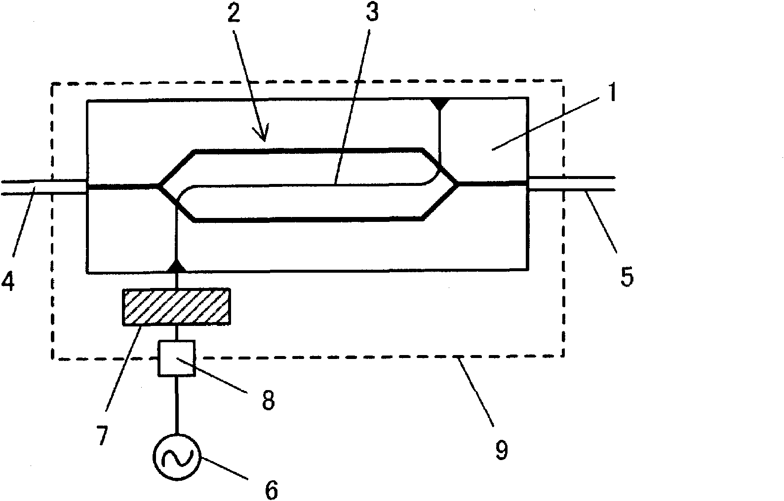
[0011] However, when the impedance of the optical waveguide element, particularly the modulation electrode 3, is different from the impedance of the external signal line of the optical waveguide element module, the modulation signal is reflected as described above, and it is difficult to efficiently apply the modulation signal to the modulation electrode.

Method used


Image

  • Optical waveguide element module
  • Optical waveguide element module
  • Optical waveguide element module

Examples


Embodiment Construction

[0053] Hereinafter, the present invention will be explained in detail using preferred examples.

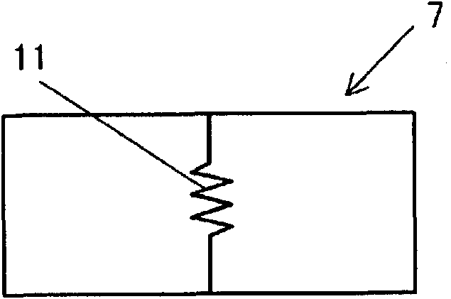
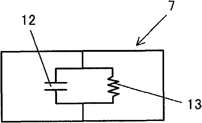
[0054] An optical waveguide element module of the present invention includes: an optical waveguide element including a substrate composed of a material having an electro-optical effect, an optical waveguide formed on the substrate, and a modulation for modulating light waves propagating in the optical waveguide An electrode; a connector connected to an external signal line for inputting a modulation signal to the modulation electrode; and a relay line connecting the connector and the modulation electrode and formed on a relay substrate, the optical waveguide element module is characterized in that: The impedance of the relay line changes stepwise or continuously to suppress the reflection of the modulated signal in the optical waveguide element module.

[0055] In addition to adjusting the impedance of the relay line formed on the relay substrate 7, the optical waveguide element module...


PUM


Abstract

Provided is an optical waveguide element module which suppresses reflection of a modulation signal and attenuation of a modulation signal, even when an impedance of a modulation electrode of an optical waveguide element and an impedance of a transmission line for inputting the modulation signal from the external of the optical waveguide element are different from each other. The optical waveguide element module is provided with an optical waveguide element, which has a substrate (1) composed of a material having electro-optical effects, an optical waveguide (2) formed on the substrate, and a modulation electrode (3) which modules optical waves propagating in the optical waveguide; a connector (8), wherein an external signal line which inputs the modulation signal to the modulation electrode is connected to the modulation electrode; and a relay line which connects the connector and the modulation electrode and is formed on a relay substrate (7). Impedance of the relay line changes stepwise or continuously, and reflection of the modulation signal in the optical waveguide element module is suppressed.

Description

Technical field [0001] The present invention relates to an optical waveguide element module, and more particularly, to an optical waveguide element module having a connector and a relay line. The connector is connected to an external signal line that inputs a modulation signal to a modulation electrode of the optical waveguide element. The connector and the modulation electrode are connected, and are formed on the relay substrate. Background technique [0002] In the field of optical communication and optical measurement, optical waveguide elements in which optical waveguides are formed on a substrate having an electro-optical effect, such as optical modulators, have been widely used as a means of controlling light waves. [0003] These optical waveguide elements are provided with modulation electrodes that modulate light waves propagating in the optical waveguide, and a modulation signal is input to the modulation electrodes through a connector connected to an external signal line...

Claims


Application Information

Patent Timeline
Patent Type & Authority Applications(China)
IPC IPC(8): G02F1/03G02F1/035
CPCG02F2201/127G02F1/2255G02F1/0356G02F2201/122
Inventor 清水亮菅又徹
Owner SUMITOMO OSAKA CEMENT CO LTD
Learn More