Fiber-optic cable alignment system

A technology of optical fiber cable and optical fiber, applied in the field of electro-optical converter and optical transmission device

Inactive Publication Date: 2004-07-07
SANMINA-SCI CORPORATION
View PDF0 Cites 13 Cited by
  • Summary
  • Abstract
  • Description
  • Claims
  • Application Information

AI Technical Summary

Problems solved by technology

[0011] In particular, it is an object of the present invention to provide expanded beam terminations and connectors and c

Method used


Image

  • Fiber-optic cable alignment system
  • Fiber-optic cable alignment system
  • Fiber-optic cable alignment system

Examples


Example Embodiment

[0054] terminal

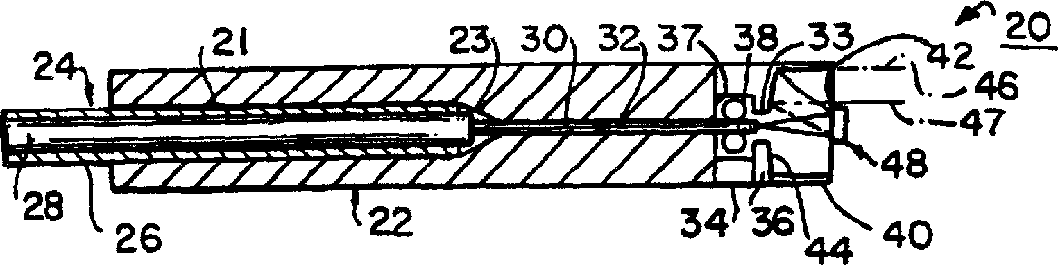
[0055] figure 1 is a cross-sectional view of a fiber optic cable termination 20 constructed in accordance with the present invention.

[0056] Termination 20 includes a standard ceramic ferrule 22 with a larger hole 21 that tapers at 23 to form a significantly smaller fiber conductor path 32 .

[0057] Compliant with the ferrule 22 are the ends of the fiber optic cable 24 including a single mode optical fiber 30 extending through the passageway 32 and a coating 28 having a different refractive index than the fiber optic cable core 30 and a final outer protective coating 26 . Typical dimensions of the cable are: the outer diameter of the cable with coating 26 is 250 microns; the diameter of the cable without coating 26 is 125 microns; and the diameter of the optical fiber or core 30 is 8 microns.

[0058] The diameter of the cable is relatively small; in particular, the diameter of the core is only 0.008 mm (about 0.0003 inches). Therefore, it is difficul...


PUM


Abstract

A system of reflectors is used to form a beam-expanding and collimating terminus (20) and coupler (59) for fiberoptic cables and electro-optic transducer devices, including radiation sources and/or detectors. Alignment of optical cores (30) of the fiber-optic cables or the reflector system with a transducer is provided by coupling a magnetic member to the core or reflector system (40) and applying a controllable magnetic field to provide alignment, then fixing the components by the use of light-curable epoxy. A reflector collimator/beam spreader are visually aligned with a source, in addition to or instead of an electrical detector, in order to avoid the need to send a signal through the system to a detector when aligning components. Reflections at an air-to-solid interface in a multiple reflector optical device are suppressed by giving the output surface of the device a sligthly curved surface to deflect the reflections away from the optical axis (77).

Description

technical field [0001] The present invention relates to electro-optic converters and light transmission devices, in particular to luminescence detection converters and their light transmission systems, and to devices and methods for aligning such systems and converters. The present invention also relates to fiber optic cables, and more particularly to terminals, connectors, alignment devices, and optical systems and methods for terminating fiber optic cables. Background technique [0002] Setting up optical transmission systems in the use of electro-optic converters has long been problematic, especially in communication systems using fiber optic cables for transmission. [0003] The extremely small diameter beams being transmitted and the small size semiconductor devices often used to generate or detect signals have complicated the coupling of electro-optic converters. Any accumulation of foreign matter such as dirt and dust on the optical path of the signal can seriously c...

Claims


Application Information

Patent Timeline
IPC IPC(8): G02B6/26G02B6/32G02B6/38G02B6/42G02B17/00H01L31/10H01L31/107H01L33/00H01L33/44H01L33/58H01S5/022
CPCG02B6/42G02B6/32G02B6/38G02B17/00H01S5/022H01L33/00H01L31/10G02B6/26H01L31/107G02B19/0019G02B6/264H01L2924/0002H01L2924/00
Inventor D·R·珀特D·E·洛伊德A·H·维海塞R·B·约翰逊
Owner SANMINA-SCI CORPORATION
Why Eureka
Try Eureka