In-vehicle camera apparatus enabling recognition of tail lamp of distant preceding vehicle

A technology for cameras and motor vehicles, which is applied in the directions of cameras, camera bodies, headlights, etc., and can solve the problems of blurred images, unclear signal/noise ratio, reduction, and inability to reliably identify taillights.

Active Publication Date: 2011-11-09
DENSO CORP
View PDF6 Cites 13 Cited by
  • Summary
  • Abstract
  • Description
  • Claims
  • Application Information

AI Technical Summary

Problems solved by technology

However, this results in blurry images captured by the camera unit and a reduced signal / noise ratio, making it impossible to reliably identify the taillights of other vehicles from the captured images

Method used


Image

  • In-vehicle camera apparatus enabling recognition of tail lamp of distant preceding vehicle
  • In-vehicle camera apparatus enabling recognition of tail lamp of distant preceding vehicle
  • In-vehicle camera apparatus enabling recognition of tail lamp of distant preceding vehicle

Examples


no. 2 example

[0050] will refer to Figure 5 and Figure 6 A second embodiment is described. Figure 5 A general configuration of the beam splitting filter 70 of the present embodiment, which is a modified form of the beam splitting filter 40 of the first embodiment, is shown. Figure 6 A general configuration of the vehicle-mounted camera device 7 of the present embodiment is shown. Since the second embodiment differs from the first embodiment only in the beam splitting filter 70 and the image sensor 10 , only the beam splitting filter 70 and the image sensor 10 will be described in detail below.

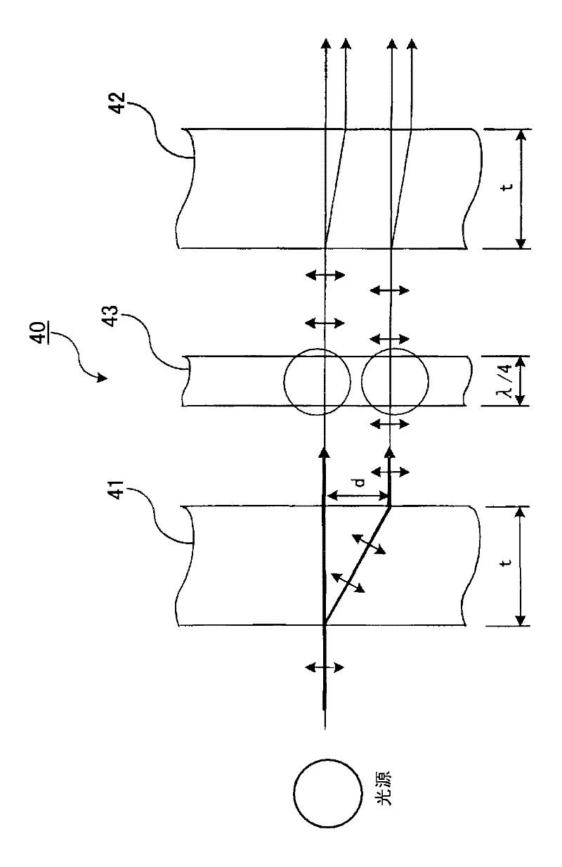
[0051] Such as Figure 5 As shown in , the difference between the beam splitting filter 70 of this embodiment and the beam splitting filter of the first embodiment is that the 1 / 4 wave plate 43 is removed. In addition, the image sensor 60 of the RGB Bayer array 18 of the second embodiment is relative to a horizontal plane parallel to the optical axis of the lens assembly 20 (that is, a plane...

no. 3 example

[0055] will first refer to Figure 7 An embodiment of the headlight control device 100 for performing automatic control of switching between high beam and low beam conditions of vehicle headlights will be described as an overall configuration in . Such as Figure 7As shown in , the headlight control device 100 includes an in-vehicle image processing device 1 and a headlight switching section 90 . The vehicle-mounted image processing device 1 is formed of the vehicle-mounted camera device 5 and the image processing section 80, however, the vehicle-mounted camera device 7 in the second embodiment may also be used instead. The image processing section 80 includes a microcomputer having a CPU, ROM, RAM, and an I / O section (not shown in the figure), which repeatedly executes processing routines according to programs stored in the ROM. The processing routine basically consists of four successive stages denoted (A), (B), (C) and (D) as follows:

[0056] (A) acquire an image from t...

no. 1 example

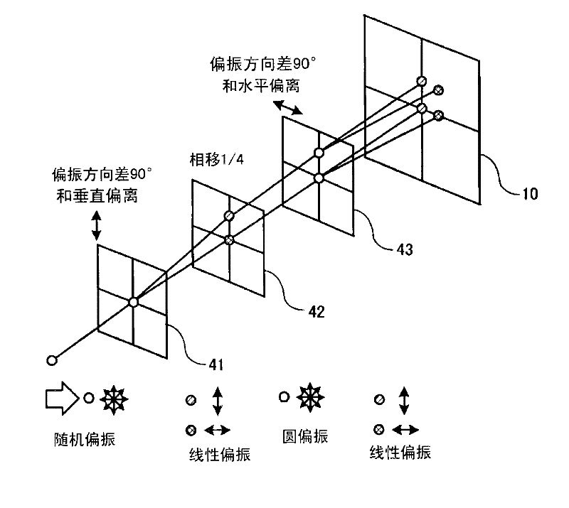
[0070] For the first embodiment, a 2×2 set of four light spots (for example, four light spots corresponding to light beams originating from distant taillights) is formed on corresponding adjacent RGB pixels of the RGB Bayer array 18 . For this embodiment, the plane of the RGB Bayer array 18 is at right angles to the horizontal (at right angles to the optical axis of the lens assembly 20). This condition is Figure 9 exemplified in part (a) of . However, it is also possible to displace the first polarizing beam splitter 41 or the second polarizing beam splitter 42 to a certain extent around the diagonal angle between two opposite corners, so that the four spots become diagonally shifted to Figure 9 The states shown in part (b) of , simultaneously fall on different respective adjacent pixels.


PUM


Abstract

The invention relates to an in-vehicle camera apparatus enabling recognition of a tail lamp of a distant preceding vehicle. The camera apparatus installated on a vehicle includes an image sensor having a RGB Bayer array of pixel sensors and a beam-splitting optical filter disposed between the camera lens assembly and the Bayer array. An incident light beam from a source such as a distant vehicle tail lamp becomes split into a plurality of light beams which become focused on respectively separate pixel sensors. Since the color of the light source is detected based on a plurality of pixel sensors, erroneous detection due to light falling on only a single R, G or B pixel sensor is prevented.

Description

technical field [0001] The present invention relates to a camera device for mounting on a subject vehicle to achieve a reliable distinction between a red light source consisting of the taillights of a vehicle ahead and an orange light source consisting of another vehicle's headlights or reflectors. [0002] In particular, the invention relates to a device whereby the taillights of a vehicle ahead can be reliably identified within a captured image even when the vehicle ahead is very far away from the subject vehicle. Background technique [0003] Systems known as AHB (Automatic High Beam) systems are known which automatically switch the vehicle's headlights between high and low beam conditions. This form of automatic headlight control is sometimes called Hi-Lo control. [0004] Such an AHB system uses an on-board camera device installed in a subject vehicle (where "camera device" as used herein refers to a general electronic type of image capture device) Differentiate betwe...

Claims


Application Information

Patent Timeline
Patent Type & Authority Applications(China)
IPC IPC(8): H04N5/232G03B17/12G03B11/04G02B27/28
CPCG02B1/113G01J3/50G02B13/001B60Q2300/41G02B27/283H04N5/2254G02B5/208H04N9/097H04N9/045G03B33/04H04N23/16H04N25/134
Inventor 木村贵之照井武和
Owner DENSO CORP
Why Eureka
Try Eureka