Holographic recording medium

a recording medium and holographic technology, applied in the field of holographic recording mediums, can solve the problems of generating noise in the recorded signal or the reproduced signal, affecting the quality of the recorded signal,

Inactive Publication Date: 2004-04-08
TDK CORPARATION
View PDF6 Cites 14 Cited by
  • Summary
  • Abstract
  • Description
  • Claims
  • Application Information

AI Technical Summary

Problems solved by technology

However, if an antireflection film is provided on the surface of the substrate to greatly suppress the reflection of the laser beams by the surface of the substrate, the light reflected by the surface of the substrate when the position control beam is projected onto the concavo-convex pattern formed on the surface of the substrate is not modulated in a desired manner and, therefore, it becomes difficult to position the object beam and the reference beam or the reference beam, or detect the address of a region in which data are being recorded or from which data are

Method used


Image

  • Holographic recording medium
  • Holographic recording medium
  • Holographic recording medium

Examples


working example 1

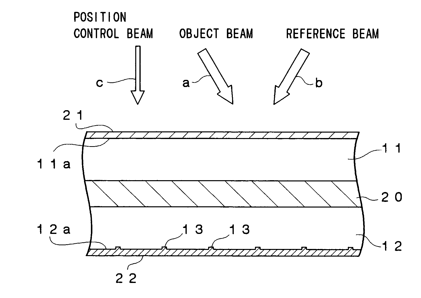
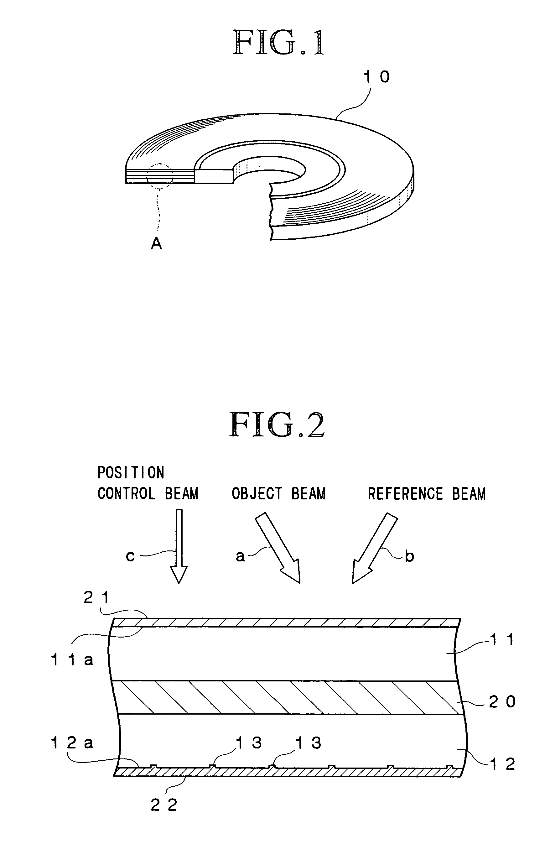
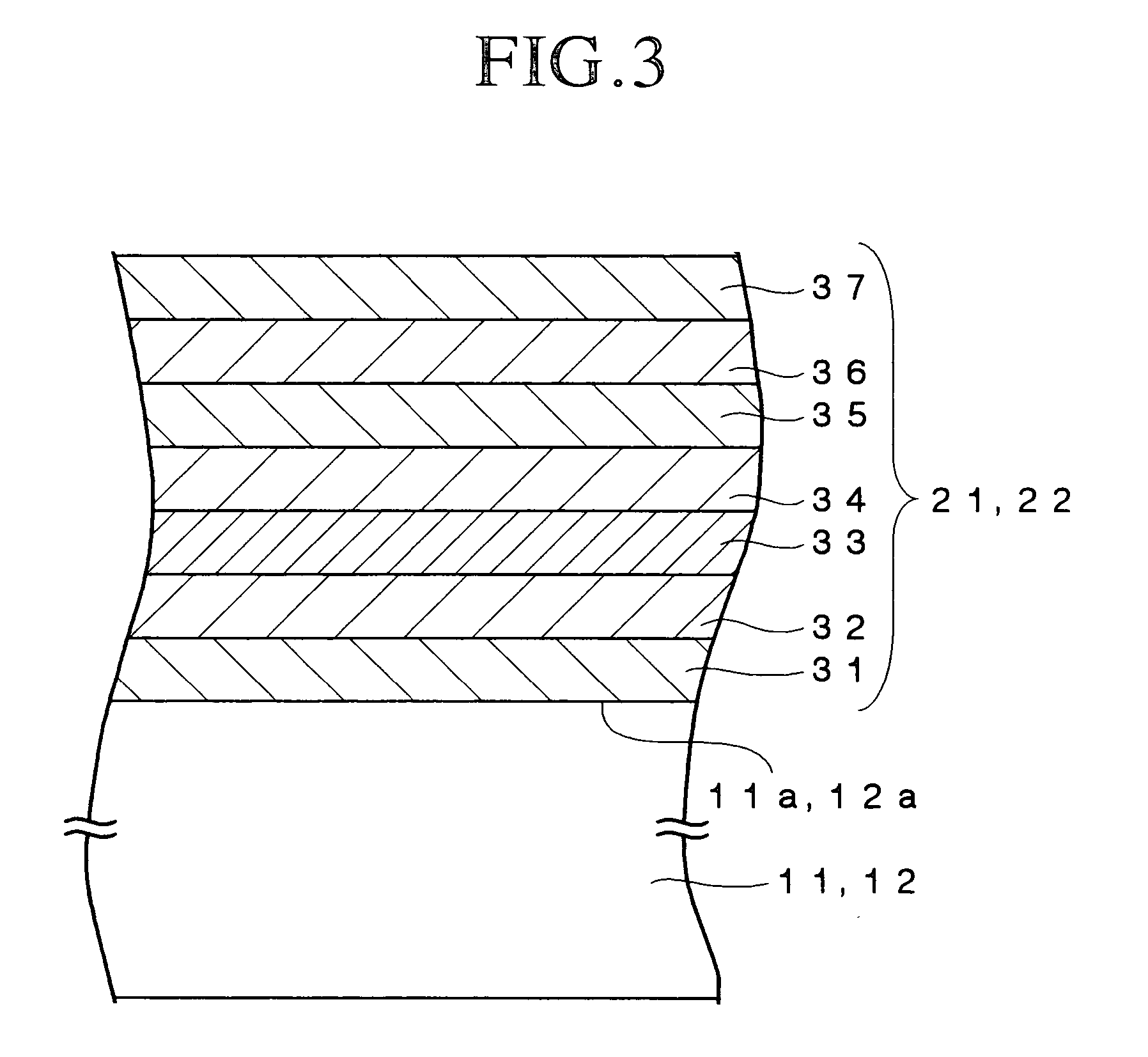
[0115] An amorphous polyolefin substrate having a thickness of 0.6 mm and a refractive index of 1.52 was prepared and an inorganic film having a thickness of 87 nm and a refractive index of 1.39 and made of a mixture of MgF.sub.2 and SiO.sub.2, an inorganic film having a thickness of 91 nm and a refractive index of 1.75 and made of Y.sub.2O.sub.3, an inorganic film having a thickness of 66 nm and a refractive index of 2.40 and made of TiO.sub.2, an inorganic film having a thickness of 76 nm and a refractive index of 1.75 and made of Y.sub.2O.sub.3, an inorganic film having a thickness of 129 nm and a refractive index of 1.39 and made of a mixture of MgF.sub.2 and SiO.sub.2, an inorganic film having a thickness of 94 nm and a refractive index of 1.75 and made of Y.sub.2O.sub.3, and an inorganic film having a thickness of 110 nm and a refractive index of 1.39 and made of a mixture of MgF.sub.2 and SiO.sub.2 were formed in this order on the amorphous polyolefin substrate using a sputte...

working example 2

[0125] A sample #4 was fabricated in the manner of the sample #1 except that a soda lime glass substrate having a thickness of 0.6 mm and a refractive index of 1.52 was employed instead of the amorphous polyolefin substrate, and a sample #5 was fabricated in the manner of the sample #2 except that a soda lime glass substrate having a thickness of 0.6 mm and a refractive index of 1.52 was employed instead of the amorphous polyolefin substrate.

[0126] When the relationship between the reflection coefficients of the sample #4 and the sample #5 and the wavelength .lambda. of a laser beam were measured, similar results to those for the sample #1 and the sample #2 were obtained.

working example 3

[0127] The reflection coefficients of the samples #1, #2 and #3 were measured by projecting a double YAG laser beam having a wavelength of 532 nm thereonto at various incidence angles.

[0128] The measurement results for the sample #1, sample #2 and sample #3 are shown in FIGS. 7, 8 and 9, respectively.

[0129] As shown in FIGS. 7 to 9, it was found that even when the incidence angle of the laser beam was varied over a wide range from 0 to 60 degrees, the reflection coefficients of the samples #1, #2 and #3 remained substantially equal to or lower than 0.5% and did not exceed 1.0%.


PUM


Abstract

A holographic recording medium includes a holographic recording carrier including a first light transmittable substrate, a second light transmittable substrate and a holographic recording layer sandwiched therebetween, a first antireflection film formed on the surface of the first light transmittable substrate and a second antireflection film formed on the surface of the second light transmittable substrate, and optical characteristics of the first antireflection film and those of the second antireflection film are determined to be different from each other the thus constituted holographic recording medium can achieves improved data recording characteristics and data reproducing characteristics using an object beam and a reference beam, and concurrently enables desired positioning of an object beam and a reference beam, or only the reference beam, and detection of the address of the region in which data are being recorded or from which data are being reproduced using a position control beam.

Description

[0001] The present invention relates to a holographic recording medium and, particularly, to a holographic recording medium in which data can be three-dimensionally recorded as a hologram.DESCRIPTION OF THE PRIOR ART[0002] Write-once type optical recording media such as the CD-R and DVD-R and data rewritable type optical recording media such as CD-RW and DVD-RW have been widely used as recording media for recording digital data. When data are to be recorded in one of these conventional optical recording media, a laser beam whose intensity is modulated is projected onto a recording layer of the optical recording medium, thereby chemically and / or physically changing the recording layer locally to form a recording mark. Data are constituted by the length (record mark length) between the front edge and the rear edge of the record mark and the length (blank length) between the rear edge of the record mark and the front edge of a next record mark. Therefore, in these optical recording med...

Claims


Application Information

Patent Timeline
IPC IPC(8): G11B7/0065G11B7/007G11B7/24044G11B7/252G11B7/253G11B7/2533G11B7/254G11B7/2548
CPCG11B7/0065G11B7/00745G11B7/0938G11B7/24044G11B2007/25417G11B7/2533G11B7/2548G11B2007/25411G11B2007/25414G11B7/252
Inventor MIZUSHIMA, TETSURO
Owner TDK CORPARATION
Why Eureka
Try Eureka