
Wire winding device

A wire winding device and wire reel technology, which is applied in the directions of electromechanical devices, coil manufacturing, transportation and packaging, can solve problems such as poor ability to suppress tension changes, and achieve the effect of shortening time.

Inactive Publication Date: 2011-05-18
HONDA MOTOR CO LTD
View PDF1 Cites 10 Cited by
  • Summary
  • Abstract
  • Description
  • Claims
  • Application Information

AI Technical Summary

Problems solved by technology

[0007] However, with such a tensioning mechanism using a spring or a damper, since the tension adjustment range is determined solely by the spring constant, the ability to suppress tension changes is poor.
On the other hand, with the brake roller mechanism, it takes time to reset the brake roller and perform maintenance when changing the supply spool because it causes the wire to cross and wind around the roller multiple times

Method used


Image

  • Wire winding device
  • Wire winding device
  • Wire winding device

Examples


Embodiment Construction

[0034] Embodiments of the winding device according to the present invention will be provided below, and with reference to the attached Figures 1 to 8 Be explained.

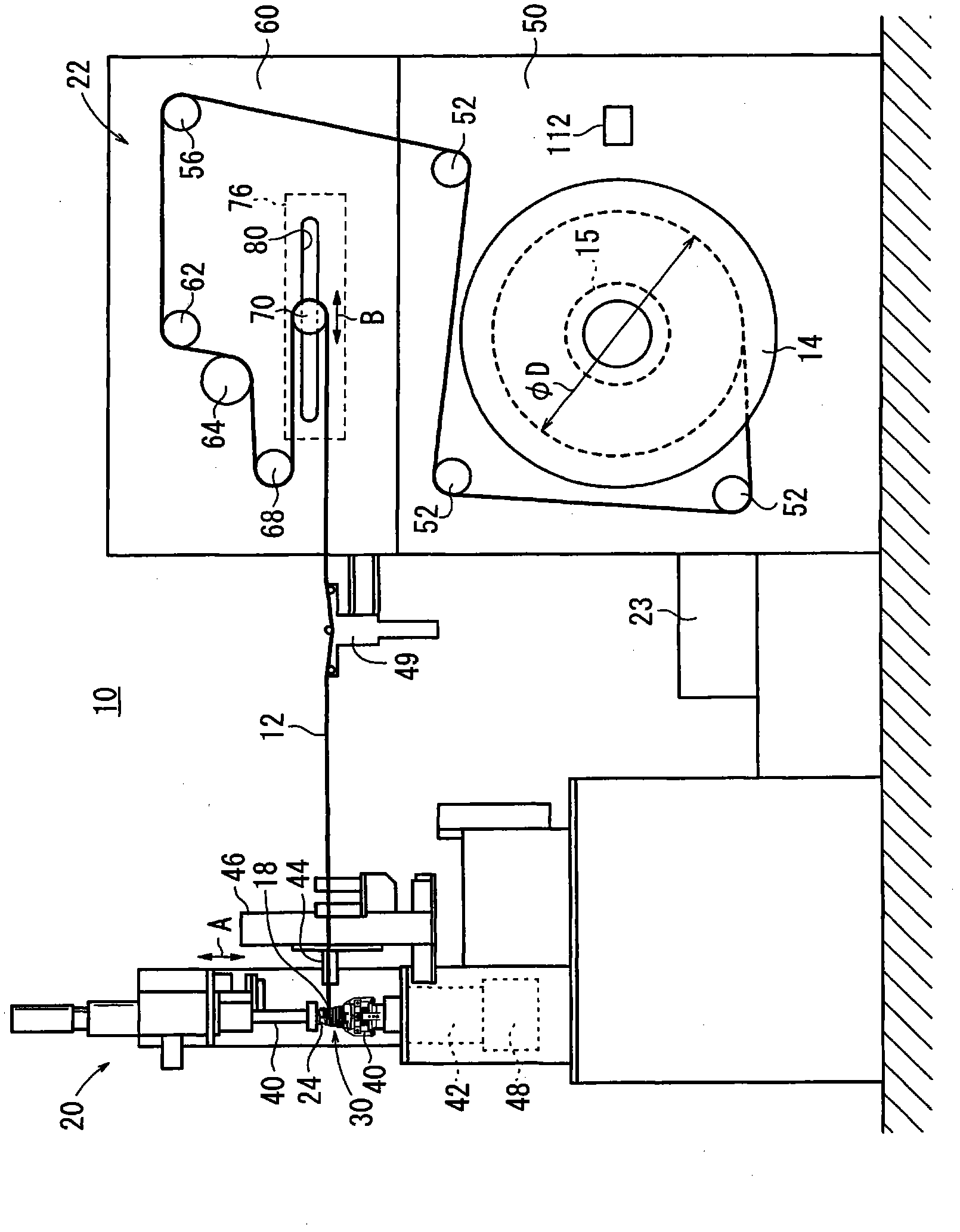
[0035] Such as figure 1 As shown, the wire winding device 10 according to the present embodiment includes: a supply reel 14 for supplying (feeding out) the wire 12 (lead wire) wound thereon; and a coil forming part 20 for The coil forming part 20 forms the coil 18 by winding the supplied wire material 12 on the bobbin 30; Tension changes generated when the wire 12 is wound; and a controller 23 used for overall control of the wire winding device 10 . The wire 12 is, for example, a copper wire with an enamel or polyurethane covering.

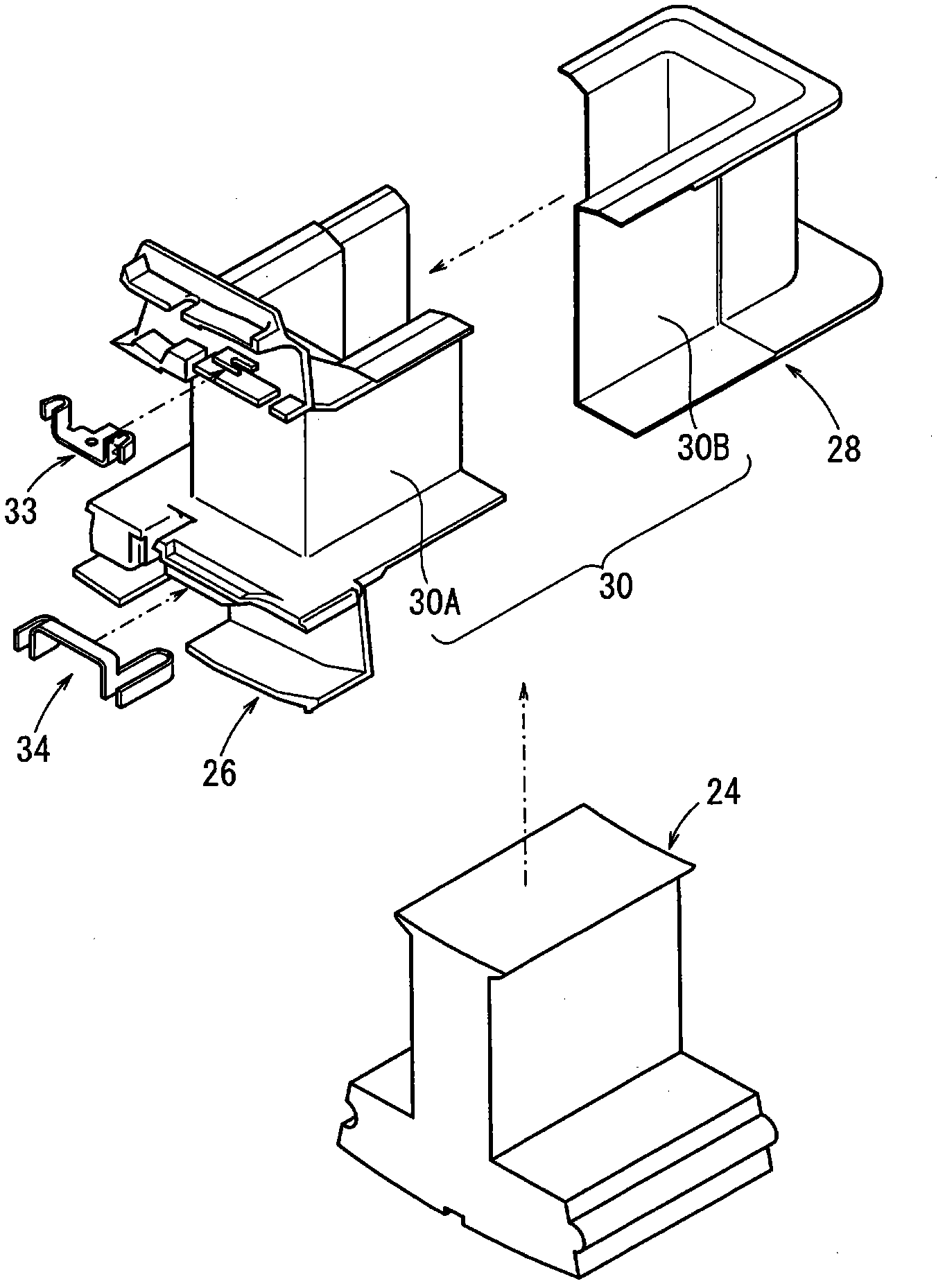
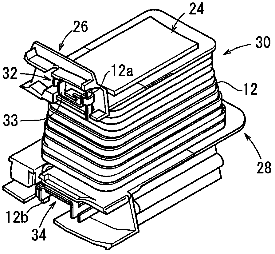
[0036] Such as figure 2 and image 3As shown, the coil 18 includes: a stack of steel plates (core) 24 consisting of a plurality of generally T-shaped steel plates that are perforated by a press and pressed together in one piece; insulated from the wire 12 wound around the stac...


PUM


Abstract

A wire winding device (10) uses a large-sized supply bobbin (14), which has a large capacity and a large diameter, to highly precisely suppress a variation in tension which variation occurs when a coil (18) is formed by winding a wire material (12) at high speed with the wire material aligned with a winding frame (30). Rotation (the number of rotation, and timing) of the supply bobbin (14) relative to rotation of the coil (18) is controlled based on the difference between the amount of take-up of the wire material (12) taken up on the winding frame (30) side and the amount of pay-out of the wire material (12) paid out from the supply bobbin (14), and the control is performed such that the amount of the take-up and the amount of the pay-out agree with each other every moment. This can highly precisely suppress a variation in tension even if there are large differences between inertia of and the diameters of the coil (18) and the supply bobbin (14).

Description

technical field [0001] The present invention relates to a wire winding device that forms a coil by winding a wire supplied from a supply bobbin on a winding frame while applying tension to the wire. Background technique [0002] For example, a stator employed in a DC brushless motor is constituted by assembling a substantially T-shaped core having an arcuate yoke and a magnetic pole portion radially extending from the yoke to the inside thereof, in a ring form. [0003] This type of stator is manufactured by clamping the yoke of the core and rotating it around the main shaft, while guiding the wire supplied from the supply bobbin through the mouth, and making the wire run along the magnetic pole portion (coil frame) The axial direction (major axis direction) reciprocates to form a multi-layer winding coil on the magnetic pole part. [0004] Generally, a wire winding device for producing coils is equipped with a supply bobbin for supplying a wire, a coil forming section for ...

Claims


Application Information

Patent Timeline
Patent Type & Authority Applications(China)
IPC IPC(8): H01F41/06H02K15/095
CPCB65H59/12H02K3/522H01F41/0612H02K15/095H02K15/0457B65H59/384H02K15/0442H01F41/064
Inventor 木村好壱钉宫卓郎架间雅仁佐佐木守田中淳子
Owner HONDA MOTOR CO LTD
Learn More