Pneumatic tongs

A pneumatic clamp and cylinder technology, applied in the field of clamps, can solve the problems of cylinder inner wall and piston rust, piston and cylinder partial wear, low connection strength, etc., and achieve the effect of small installation space, large connection surface and high connection strength

Active Publication Date: 2011-05-25
扬州兴浦机械设备有限公司
View PDF4 Cites 3 Cited by
  • Summary
  • Abstract
  • Description
  • Claims
  • Application Information

AI Technical Summary

Problems solved by technology

[0004] 1. The cylinder is composed of a cylinder head, a piston rod, a cylinder block, a piston, a return spring, etc. The cylinder block and the piston are integrally processed with steel, and the piston and the piston rod are made as a whole, which requires high precision and wastes a lot of materials. high cost
Moreover, if the user of the machine tool stops for a period of time for some reason, the inner wall of the cylinder and the piston will be rusted. When the machine is turned on again, the clamp will be stuck and will not act according to the command.
Moreover, the dynamic seal between the piston and the cylinder wall, and the dynamic seal between the piston rod and the cylinder hole all adopt O-shaped seal rings, which have poor sealing effect and short service life.
[0005] 2. Due to structural reasons, the connection surface between the cylinder and the lower caliper body is very small, and the connection strength is low
However, this structure requires a large installation space on the one hand, and on the other hand, the piston rod is subjected to a biasing force when it is working. Eccentric wear shortens its lifespan

Method used


Image

  • Pneumatic tongs
  • Pneumatic tongs
  • Pneumatic tongs

Examples


Embodiment Construction

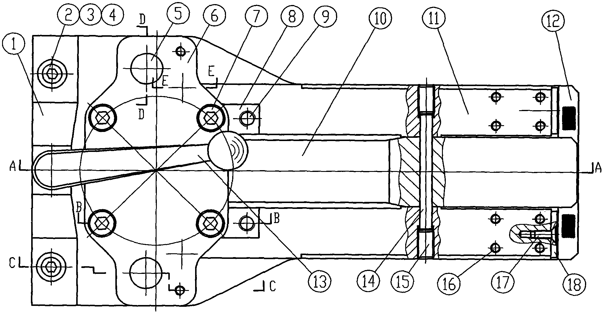
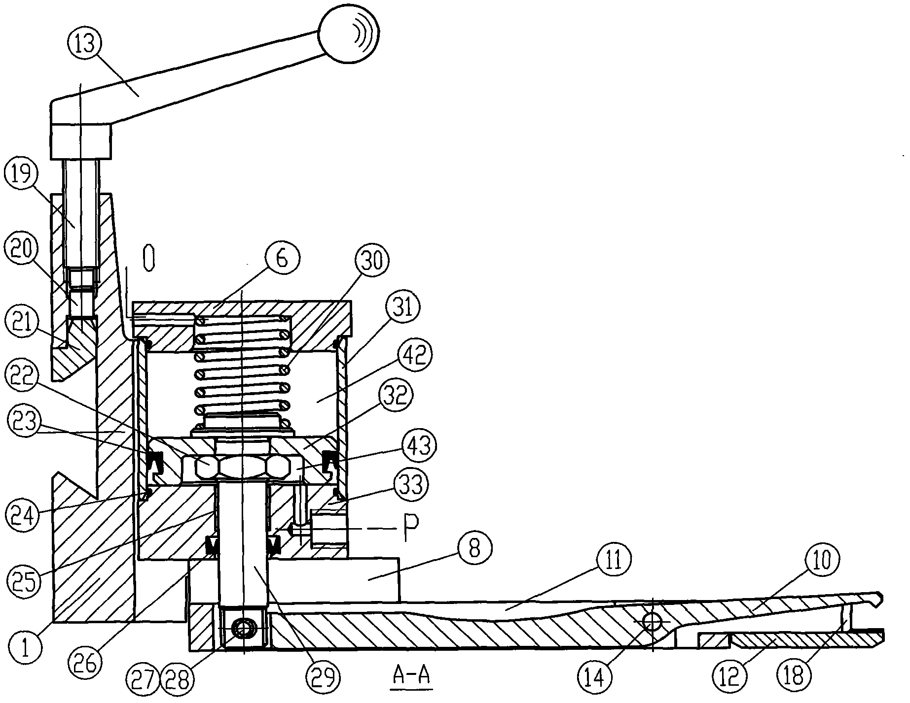
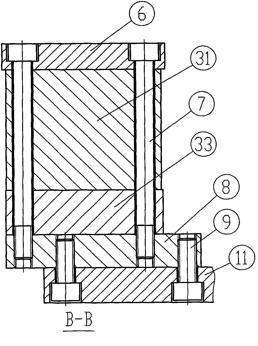
[0022] Such as figure 1 , figure 2 , image 3 , Figure 4 , Figure 5 , Image 6 As shown, a pneumatic clamp is composed of a base 1, a cylinder, an upper clamp body 10, a lower clamp body 11, etc., and the cylinder is composed of a cylinder head 6, a piston rod 29, a cylinder barrel 32, a piston 33, and a cylinder seat 34, back-moving spring 31 etc. constitute. The middle part of the upper caliper body is hingedly connected with the lower caliper body through pin shaft 14, and the rear end of the upper plier body is connected with the piston rod tail end of the cylinder through pin shaft 27. The cylinder head, cylinder barrel and cylinder seat of the cylinder are connected with four bolts 7, 4 A bolt 9 is fastened on the lower tong body through two contour pads 8, and two sliding posts 5 are arranged in series on the cylinder head, the lower tong body and the base, and two straight lines are arranged in the base hole through which the sliding posts pass. bearing37. Th...


PUM


Abstract

The invention discloses a pair of pneumatic tongs, which belongs to the technical field of machine tool clamps. The pair of pneumatic tongs comprises a base, an air cylinder, an upper tong body and a lower tong body, wherein the middle part of the upper tong body is hinged with the lower tong body through a pin shaft; and the rear end of the upper tong body is connected with the tail end of a piston rod of the air cylinder through a pin shaft. The pair of pneumatic tongs is characterized in that: an air cylinder cover, an air cylinder drum and an air cylinder base are fastened on the lower tong body through two contour pads by a bolt; two slide columns are strung on the air cylinder cover, the lower tong body and the base; a linear bearing is arranged in a base hole through which the slide columns pass; the tail end of the piston rod is a flat tail; a round waist hole is formed on the flat tail; a roller sleeve is arranged in the round waist hole; and the pin shaft connecting the rearend of the upper tong body and the tail end of the piston rod is sleeved in the roller sleeve. The pair of pneumatic tongs has a reasonable and simple structure, low material waste, low machining cost, good anti-rust function, high sealing effect and long service life and is easy to manufacture. The air cylinder is connected with the lower tong body at a plurality of points; the connection area is large; and the connection strength is high. The pair of pneumatic tongs is strong in overall rigidity; the deformation displacement of a tong tooth part during working is small; and the service lifeis long.

Description

technical field [0001] The invention relates to a clamp used for clamping a workpiece (plate material) by a numerically controlled stamping machine tool, belonging to the technical field of machine tool clamps. Background technique [0002] Most of the clamps used by the existing CNC stamping machine tools to clamp workpieces use compressed air as the power. The piston rod in the cylinder drives the tail of the upper clamp body to move, so that the upper clamp body rotates relative to the lower clamp body, and the front teeth of the upper clamp body press To the tooth plate installed under the front end of the lower pliers body, thereby pressing the plate between the front teeth of the upper pliers body and the tooth plate, to realize the clamping of the workpiece. [0003] This type of clamp usually has the following problems: [0004] 1. The cylinder is composed of a cylinder head, a piston rod, a cylinder block, a piston, a return spring, etc. The cylinder block and the ...

Claims


Application Information

Patent Timeline
Patent Type & Authority Applications(China)
IPC IPC(8): B23Q3/06
Inventor 孙钊朱兴龙陈建新
Owner 扬州兴浦机械设备有限公司
Why Eureka
Try Eureka