Device for manufacturing nano laminated composite material

A composite material and nano-laminated technology, which is applied in the field of advanced material processing, can solve the problems of flow channel design difficulties, layered structure damage due to flow boundary dragging, and the number of series connections should not be too large, etc.

Active Publication Date: 2011-05-25
BEIJING UNIV OF CHEM TECH
View PDF4 Cites 35 Cited by
  • Summary
  • Abstract
  • Description
  • Claims
  • Application Information

AI Technical Summary

Problems solved by technology

However, if this technical scheme is used to obtain nano-scale composite materials (interlayer thickness ≤ 100nm) in an extrusion die of 1mm, more than 10 splitters in series are required, because each time the melt passes through a split It is necessary to overcome a large flow resistance, resulting in a drop in pressure, and the dragging effect of the flow boundary will also cause a certain degree of damage to the layered struct

Method used


Image

  • Device for manufacturing nano laminated composite material
  • Device for manufacturing nano laminated composite material
  • Device for manufacturing nano laminated composite material

Examples


Embodiment 1

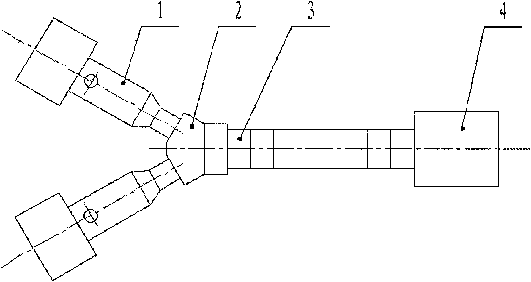
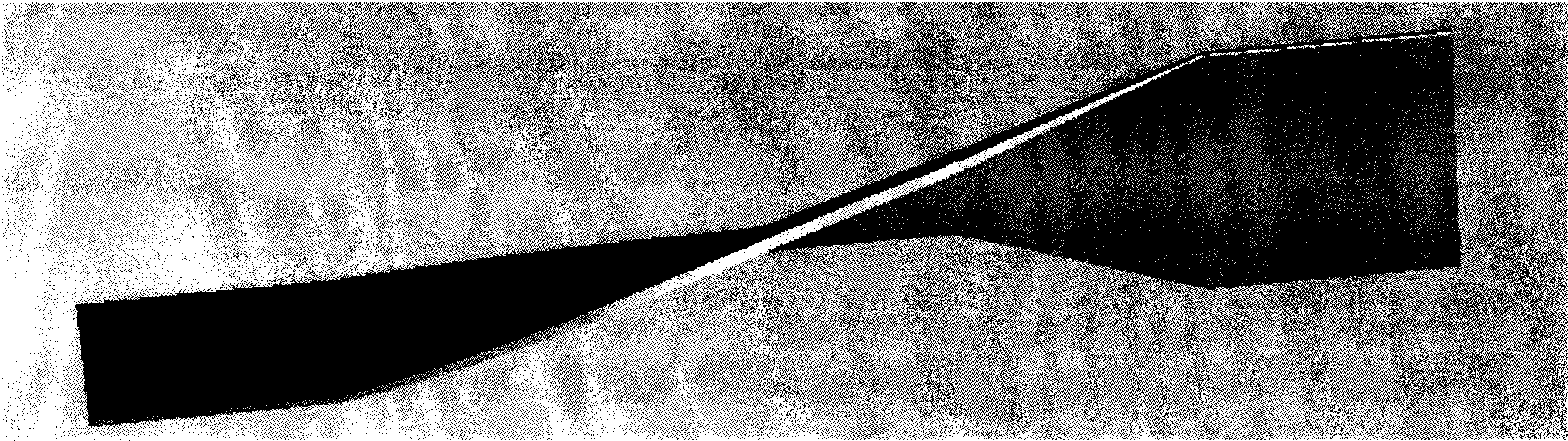
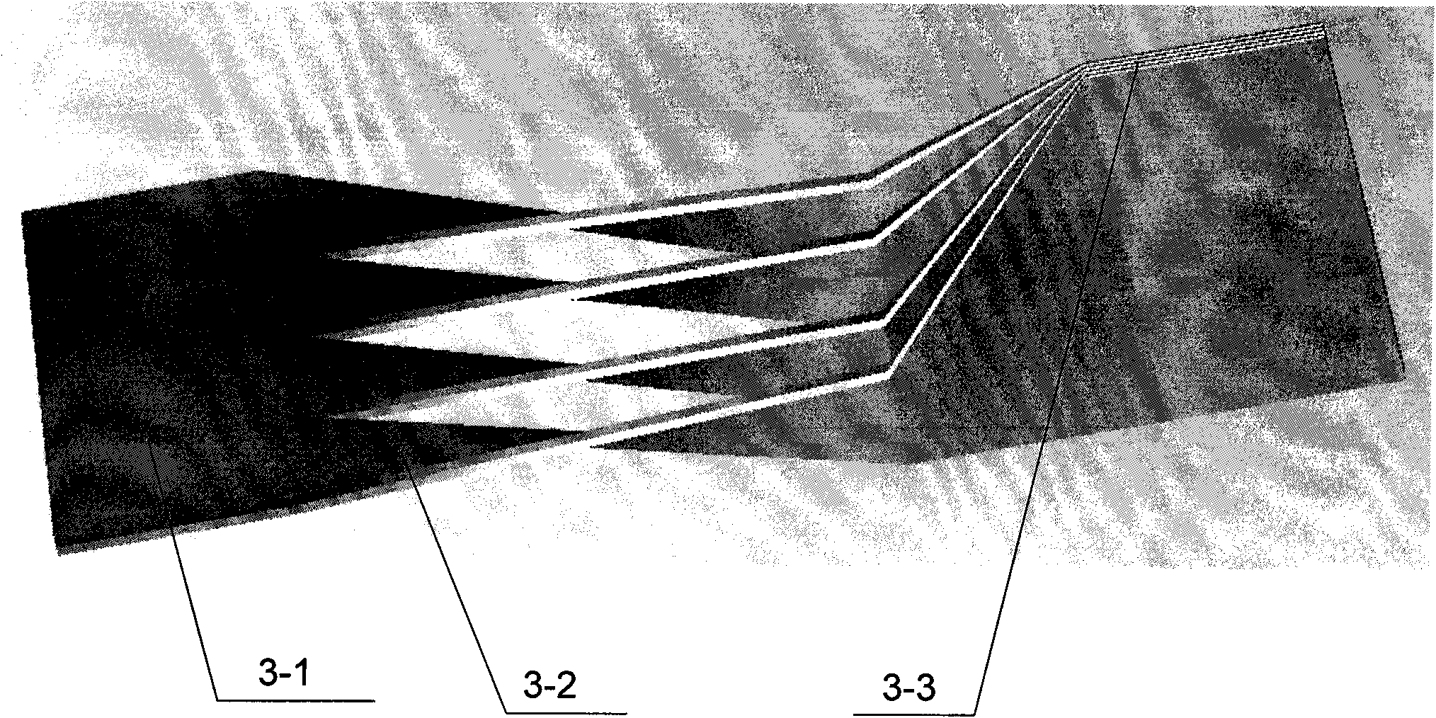
[0014] A device for preparing nano-laminated composite materials disclosed in this embodiment, the overall shape is as shown in the attached figure 1 As shown, it includes a plasticizing feeding device 1 with two or more extruders, a confluence 2, a laminated composite generator 3, and a molding device 4, which are connected in series in sequence. The main functional structure of the laminated compound generator 3 is to collect the polymer melts from n plasticizing feeding devices through the confluence 2 into n-layer polymer melts 3-1 in the confluence, and each layer melts The thickness of the body is the same, and the n-layer polymer melt 3-1 in the manifold is divided into m equal parts along the width direction when it leaves the manifold 2, and each equal part is divided into the stacked flow channel 3-1 of the laminated composite generator. 2, when they continue to flow forward, they rotate 90 degrees and widen m times, and merge into each other at the outlet end to for...

Embodiment 2

[0018] Another example of a nano-lamination composite material preparation device disclosed in this embodiment, the overall shape is as follows Figure 4 As shown, it includes a plasticizing feeding device 1, a confluence 2, a laminated composite generator 3, an injection nozzle 5 and a mold 6 with two or more injection molding machines. The injection nozzle 5 and the mold 6 form a molding device, and the plasticizing The feeding device 1, the confluence 2, the laminated composite generator 3, and the injection nozzle 5 are serially connected in sequence, and the nozzle 5 is connected with the mold 6 during injection molding. The main functional structure of the laminated composite generator 3 is to divide the n-layer polymer melt 3-1 extruded by the confluence into m equal parts along the width direction, and each equal part is divided into m equal parts in the laminated composite generator. When the stacked flow channel 3-2 continues to flow forward, it rotates 90 degrees an...


PUM


Abstract

The invention relates to a device for manufacturing a nano laminated composite material, which comprises a plastifying device, a converging device, a laminated composite generator and a molding device which are sequentially connected in series front and back, wherein the laminated composite generator is used for averagely dividing n layers of polymer melts extruded by the converging device into m equal parts along the width direction; when each equal part of melt continues to forwards flow in the laminated composite generator, the melt is rotated for 90 degrees and broadened by m times so as to mutually converge with an adjacent melt layer into a laminated structure at an outlet end; then an identical laminated composite generator is connected in series to obtain an n*m*m structure; and if k identical laminated composite generators are connected in series, a multi-layer structure composite material with n*mk layers can be obtained. In the invention, the laminated composite generators rotating for 90 degrees after melt segmentation are adopted, thus the segmentation quantity is large, the quantity of serial units can be reduced, and the melt is easy to maintain a symmetrical structure in a flow broadening and thinning process, so that the layer thickness precision is easy to guarantee, and a nano laminated composite multi-layer product can be obtained.

Description

technical field [0001] The invention belongs to the technical field of advanced material processing, and relates to a nano-lamination composite material processing device, in particular to a device for preparing multi-layer composite structure polymer materials and products by composite extrusion or composite injection molding. Background technique [0002] Layered nanocomposites have unique advantages in mechanical properties, barrier properties, electrical conductivity, optical properties, etc., and have broad application prospects, so they have become a hot research topic in the field of materials, and have achieved some research results. A series of Multilayer extrusion dies for the preparation of layered composite polymer materials. Judging from the currently published patents, the earliest US patents 3557265, 3565985, and 3884606 were applied by W.J.Shrenk et al., and later Chinese patents CN1511694A, 200610022348.6, etc. The existing patented technology basically bel...

Claims


Application Information

Patent Timeline
IPC IPC(8): B29C47/06B29C47/70B29C45/16B29C45/58
Inventor 杨卫民王德禧丁玉梅
Owner BEIJING UNIV OF CHEM TECH
Why Eureka
Try Eureka