
Impinging diffusing device

A diffuser device and sonic nozzle technology, which is applied in the direction of liquid variable displacement machinery, pump testing, machine/engine, etc., can solve the problems of poor accuracy and inconspicuous effect, and achieve easy operation, simple equipment and low cost Effect

Inactive Publication Date: 2012-05-23
BEIHANG UNIV
View PDF0 Cites 0 Cited by
  • Summary
  • Abstract
  • Description
  • Claims
  • Application Information

AI Technical Summary

Problems solved by technology

The principle of constant pressure is used in the measurement, and the dropper flowmeter supplies gas to the vacuum container. In order to reduce the jet effect of the gas ejected from the air duct, a diffuser is added at the outlet of the air duct, but the effect is not obvious. Faster results are less accurate

Method used


Image

  • Impinging diffusing device
  • Impinging diffusing device
  • Impinging diffusing device

Examples


Embodiment Construction

[0034] The present invention will be further described below in conjunction with accompanying drawing.

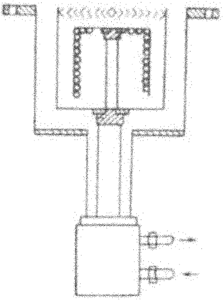
[0035] The present invention proposes a kind of mutual strike diffuser, such as Figure 6 and Figure 7 As shown, it mainly includes high-pressure gas cylinder 1, filter 2, primary pressure reducer 3, solenoid valve A4, secondary pressure reducer 5, voltage stabilizer 6, heater 7, solenoid valve B8, tee 9, sound velocity Nozzle A10, sonic nozzle B11, pressure sensor A12, temperature sensor 13, pressure sensor B14, constant pressure vacuum pump 15, built-in cryopump 16, vacuum container 17, air duct A18 and air duct B19.

[0036]The high pressure cylinder 1, filter 2, primary pressure reducer 3, solenoid valve A4, secondary pressure reducer 5, voltage stabilizer 6, heater 7 and solenoid valve B8 are connected in sequence. One end of the tee 9 is connected to the solenoid valve B8, one end is connected to the sonic nozzle A10 through the air duct A18, and the other end is c...


PUM


Abstract

The invention provides an impinging diffusing device mainly comprising a high-pressure gas cylinder, a filter, a first-level pressure reducer, a second-level pressure reducer, a pressure stabilizer, a heater, a tee joint, a sound speed nozzle A, a sound speed nozzle B, a built-in low-temperature pump, a vacuum container and the like. The impinging diffusing device is mainly applied to the pumpingspeed measurement of a large-scale built-in low-temperature pump; the gas satisfying the standard of the pumping speed measurement can be provided by a pressure stabilizing gas source; the flow of the gas can be precisely controlled by the sound speed nozzle; therefore, the influence of the jet effect of the gas at an outlet of a gas guide tube to the pumping speed measurement is reduced, and thepumping speed of the built-in low-temperature pump can be precisely measured.

Description

technical field [0001] The invention belongs to the technical field of pumping speed measurement, and in particular relates to an interaction type diffuser. Background technique [0002] Cryopump is a kind of vacuum acquisition equipment using condensation adsorption technology. The mechanism of low temperature surface pumping is mainly based on the characteristic that the saturated vapor pressure of the substance decreases as the temperature decreases, that is, the lower the temperature of the cold plate of the cryopump, the lower the temperature of various gas molecules. The lower the saturated vapor pressure of the cryopump, the gas molecules whose condensation temperature is higher than the temperature of the cold plate of the cryopump will condense on the surface of the cold plate of the cryopump, so as to achieve the purpose of pumping out the gas and obtaining a vacuum. [0003] The temperature of liquid helium at an atmospheric pressure is about 4.2K, a cold plate co...

Claims


Application Information

Patent Timeline
Patent Type & Authority Patents(China)
IPC IPC(8): F04B51/00F04B37/08
Inventor 蔡国飙王文龙凌桂龙黄本诚张国舟李晓娟
Owner BEIHANG UNIV
Learn More