
High speed burner for combustion chamber with film cooling type corrugated shell structure

A high-speed burner and shell structure technology, which is applied to gas fuel burners, burners, combustion methods, etc., can solve the problems of short service life and achieve the effects of improving service life, improving heat exchange effect, and increasing service life

Active Publication Date: 2011-05-25
HARBIN INST OF TECH
View PDF9 Cites 6 Cited by
  • Summary
  • Abstract
  • Description
  • Claims
  • Application Information

AI Technical Summary

Problems solved by technology

[0003] In order to solve the technical problem of short service life of the combustion chamber shell of the existing burner, the present invention further provides a high-speed burner with a film cooling type corrugated shell structure combustion chamber

Method used


Image

  • High speed burner for combustion chamber with film cooling type corrugated shell structure
  • High speed burner for combustion chamber with film cooling type corrugated shell structure
  • High speed burner for combustion chamber with film cooling type corrugated shell structure

Examples


specific Embodiment approach 1

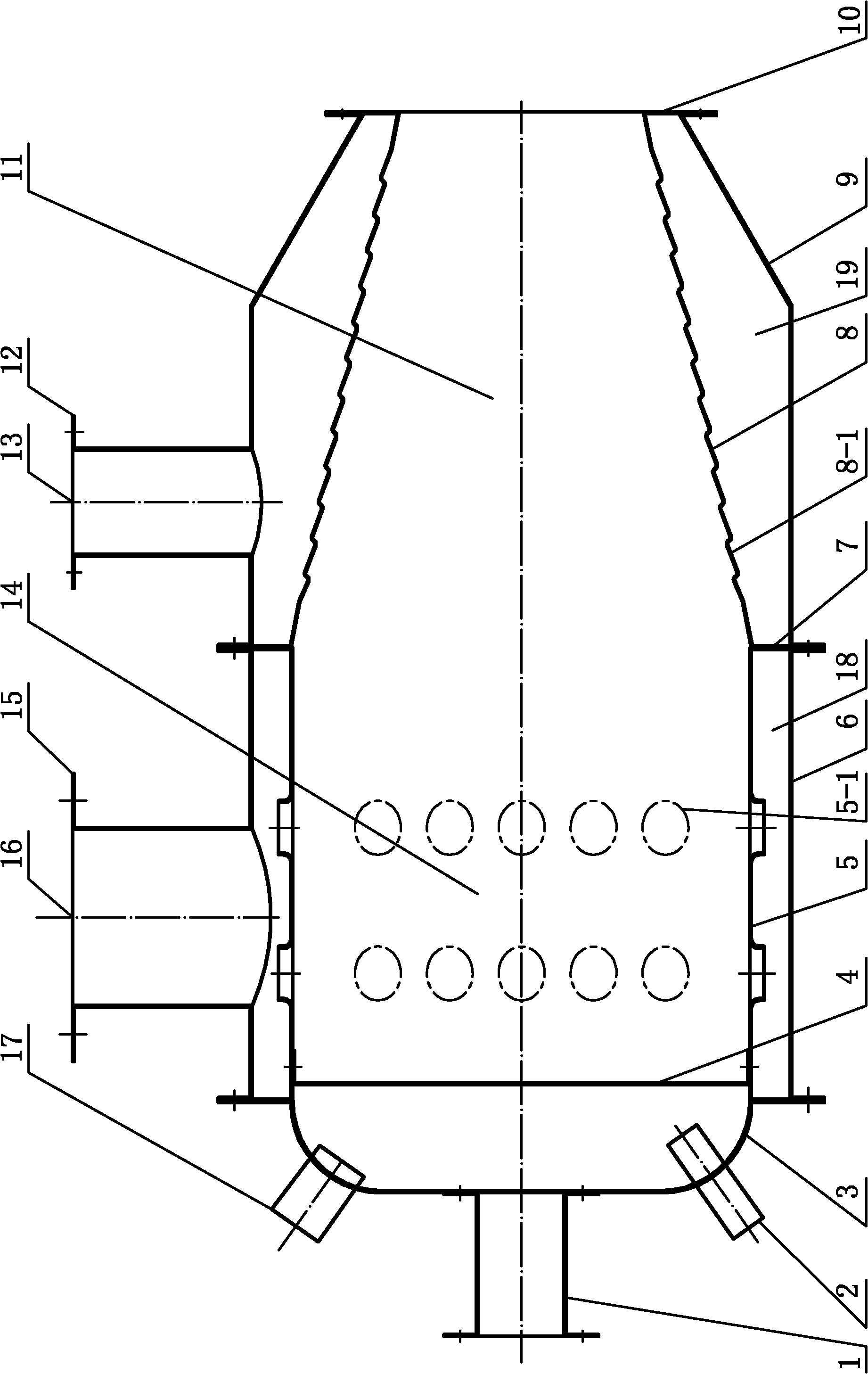
[0011] Specific implementation mode one: as Figure 1-9 As shown, the film-cooled corrugated shell structure combustion chamber high-speed burner described in this embodiment includes a high-speed burner end cover 3, a combustion chamber cylinder 5, a combustion chamber cylinder outer cover 6, and a combustion chamber housing 8 , gas inlet 1 and combustion-supporting air inlet 16, and the burner also includes a combustion chamber casing cover 9 and a secondary air inlet 13; the combustion chamber casing 8 is a conical casing whose side wall is corrugated, and the combustion chamber The longitudinal section of the side wall of the housing 8 has a corrugated structure; the combustion chamber housing 8 is uniformly distributed with a plurality of film cooling holes 8-1 (through holes); One end of the indoor cylinder 5, the other end of the combustion chamber 5 communicates with the large end of the combustion chamber shell 8, the gas inlet 1 communicates with the high-speed burne...

specific Embodiment approach 2

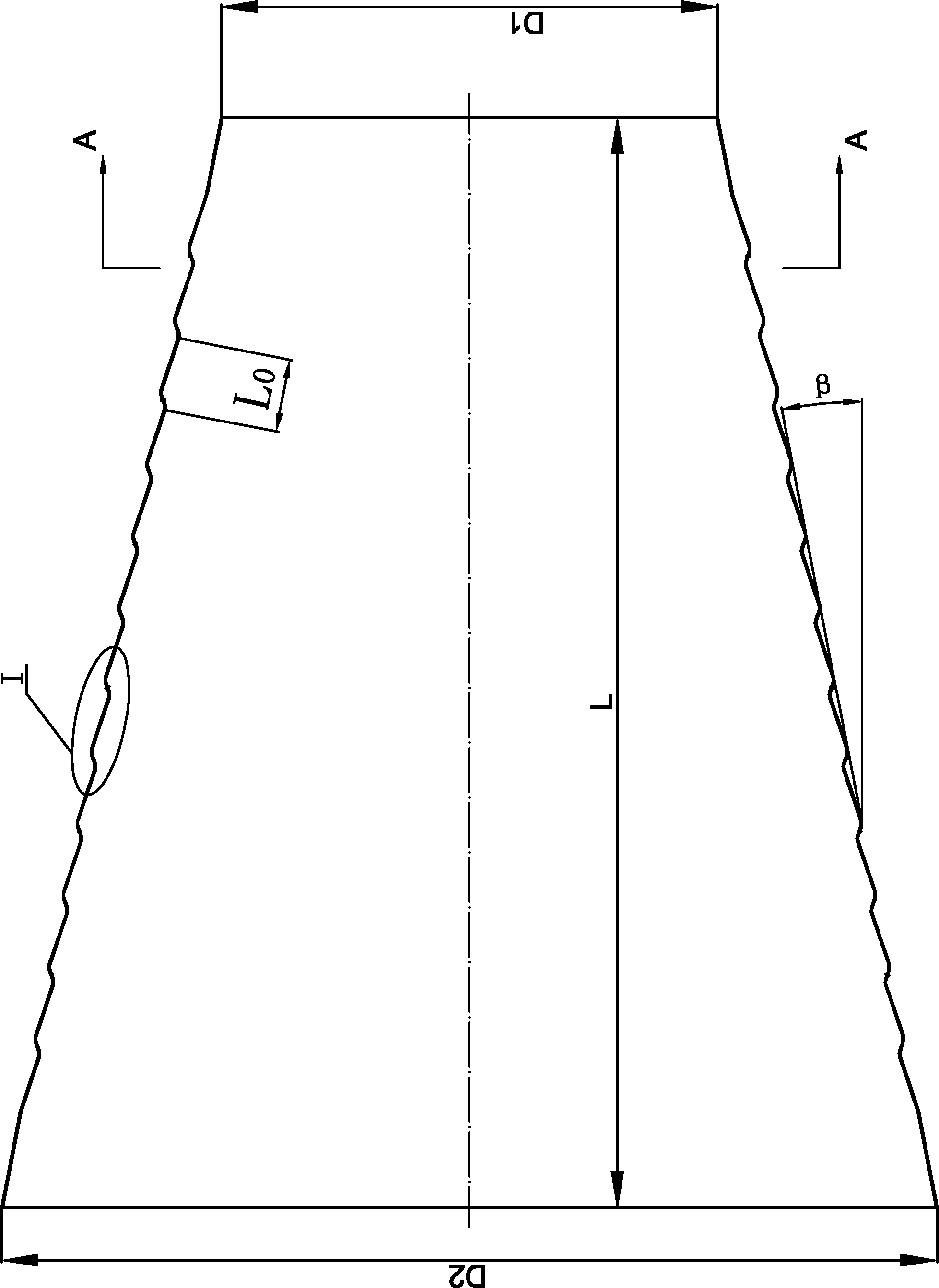
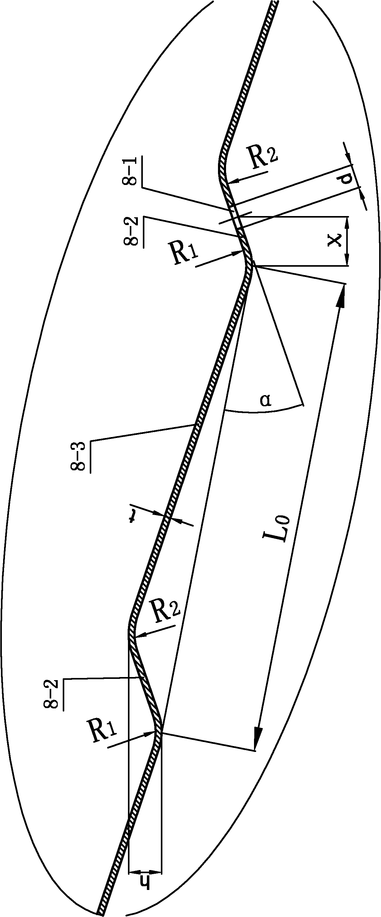
[0017] Specific implementation mode two: as Figure 2~3 As shown, the longitudinal section of the side wall of the combustion chamber housing 8 in this embodiment is formed by sequentially connecting n sections of single-section corrugations, and each single-section corrugation is composed of short corrugations 8-2 and long corrugations 8-3, each Length L of single corrugation 0 The corrugation angle α of each single-section corrugation is 25°-45°, the corrugation height h of each single-section corrugation is 2.0mm-3.0mm; the number of corrugated sections n of the combustion chamber shell 8 is determined by the single section Corrugation length L 0 and the total length L of the combustion chamber. The above parameters are all related to the cooling effect of the combustion chamber shell. The combustion chamber shell adopts a metal corrugated conical shell with film cooling holes. The corrugated structure increases the rigidity of the combustion chamber shell, and has good ...

specific Embodiment approach 3

[0018] Specific implementation mode three: as Figure 2~3 As shown, in this embodiment, the inward concave transition fillet radius R between the adjacent short corrugated ribs 8-2 and the long corrugated ribs 8-3 1 1.5mm to 2.5mm, the outwardly convex transition fillet radius R between adjacent short corrugations 8-2 and long corrugations 8-3 2 2.0mm to 2.5mm. Other components and connections are the same as those in the second embodiment.


PUM


Abstract

The invention discloses a high speed burner for a combustion chamber with a film cooling type corrugated shell structure, which relates to a high speed burner for a combustion chamber and aims to solve the technical problem of short service life of the combustion chamber shell of the conventional burner. The technical key points are that: the combustion chamber shell is a tapered shell of which the side wall is corrugated; the longitudinal section of the side wall of the combustion chamber shell has a corrugated structure; a plurality of gas film cooling holes are uniformly formed on the combustion chamber shell in a circumferential direction; the outer cover of a combustion chamber inner barrel is sleeved on the combustion chamber inner barrel; a combustion-supporting air sealed air cavity is formed between the outer cover of the combustion chamber inner barrel and the combustion chamber inner barrel; the outer cover of the combustion chamber shell is sleeved on the combustion chamber shell; a secondary air sealed air cavity is formed between the outer cover of the combustion chamber shell and the combustion chamber shell; a combustion-supporting air inlet is formed on the outer side wall of the outer over of the combustion chamber inner barrel; and a secondary air inlet is formed on the outer side wall of the outer cover of the combustion chamber shell. By adopting the corrugated tapered metal shell with the air film cooling holes, turbulence intensity can be increased, the heat exchange effect is improved, and the service life of the combustion chamber shell of the high speed burner is effectively prolonged.

Description

technical field [0001] The invention relates to a high-speed burner for a combustion chamber, in particular to a high-speed burner for a film-cooled corrugated shell structure, which belongs to the technical field of industrial furnaces. Background technique [0002] With the rapid development of the metallurgical industry and heat treatment industry, the temperature and speed requirements for the high-speed burner outlet are getting higher and higher. The combustion speed of ultra-high temperature fuel is very fast, and the heat intensity of the burner combustion chamber is very large. At present, the shell of the ultra-high temperature combustion chamber has poor resistance to dynamic loads, poor thermal shock resistance, short service life, and frequent replacement, which limits the high-speed burner to high temperature, High-speed development. Therefore, the combustion chamber housing of the existing high-speed burner has the technical problem of short service life. C...

Claims


Application Information

Patent Timeline
Patent Type & Authority Applications(China)
IPC IPC(8): F23D14/48F23D14/46
Inventor 王忠金冯福伟
Owner HARBIN INST OF TECH
Learn More