

Optics detecting device
An optical detection and spot technology, applied in the direction of optical devices, measuring devices, medical science, etc., can solve the problems of insufficient hardware resources, movement errors of the treatment bed, and low reliability, so as to increase the area of sampling area and improve the resolution accuracy , to facilitate the detection of the effect of the work
Inactive Publication Date: 2011-05-25
深圳市华盼科技有限公司
View PDF6 Cites 23 Cited by
- Summary
- Abstract
- Description
- Claims
- Application Information
AI Technical Summary
Problems solved by technology
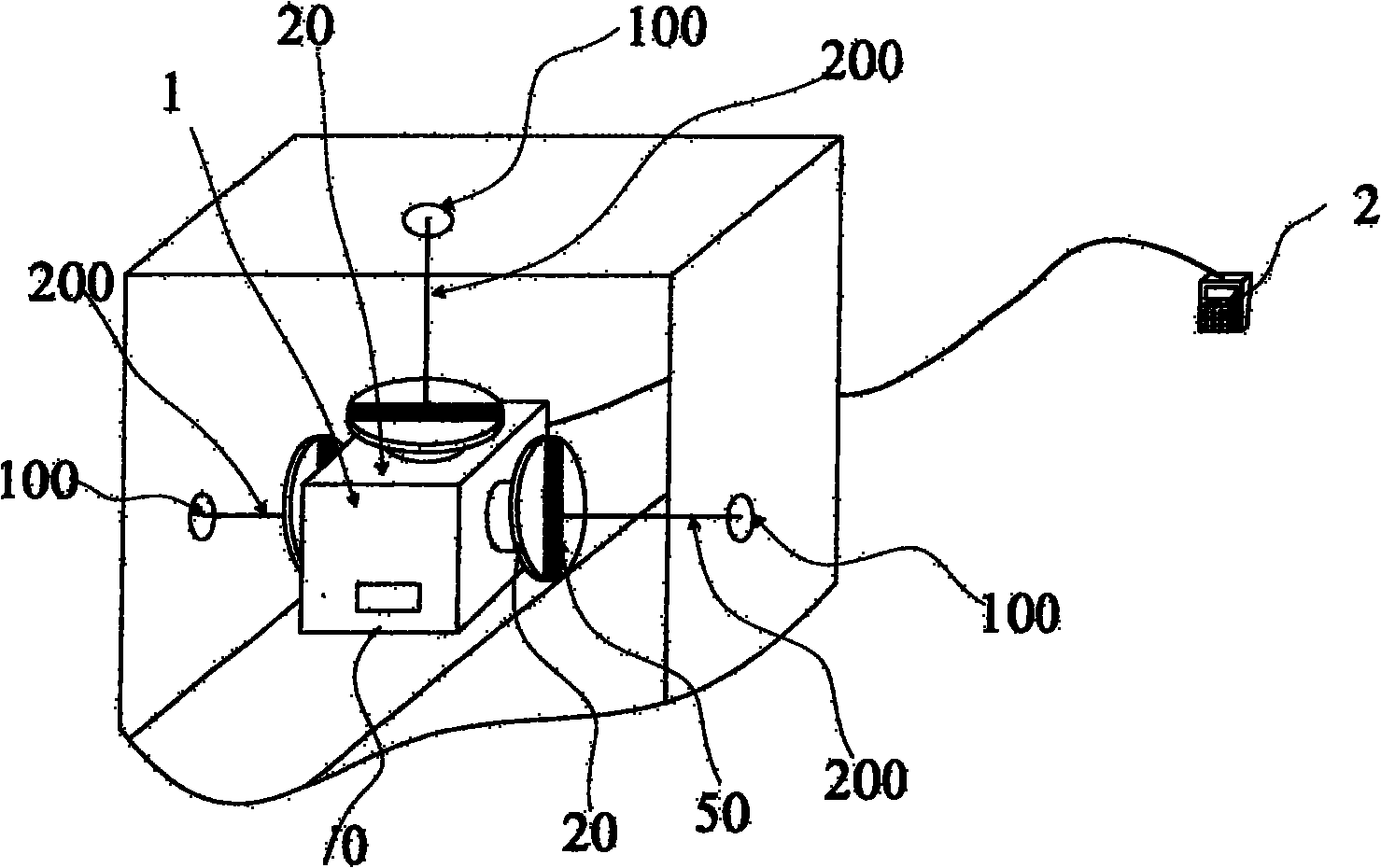
Because the left turntable, the right turntable and the top turntable 20 rotate on the axis of the main body housing 10 coordinate systems, the detection direction is limited to the vicinity of the left and right and top axis angles of view. If other directions are to be detected, the sampling mainframe 1 must be moved, so that need to reposition and introduce new errors
[0005] 2. It is necessary to move the treatment bed to cooperate with the detection of the direction of light source irradiation, and introduce movement errors of the treatment bed
Therefore, a new couch movement error is introduced
[0006] 3. During measurement, the normal angle of the sensor sampling surface 20 cannot be dynamically adjusted. Like this, it cannot be guaranteed that the sensor sampling surface 20 is perpendicular to the incident direction of the external light spot. If it is not vertical, the light spot profile irradiated on the sens
Method used
View moreImage
Smart ImageViewing Examples

Examples
 PUM
 Abstract
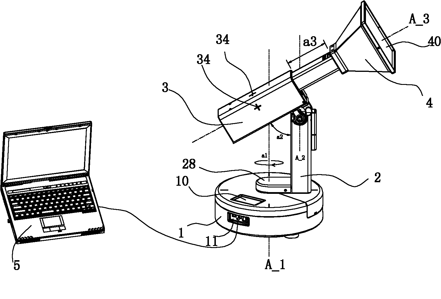
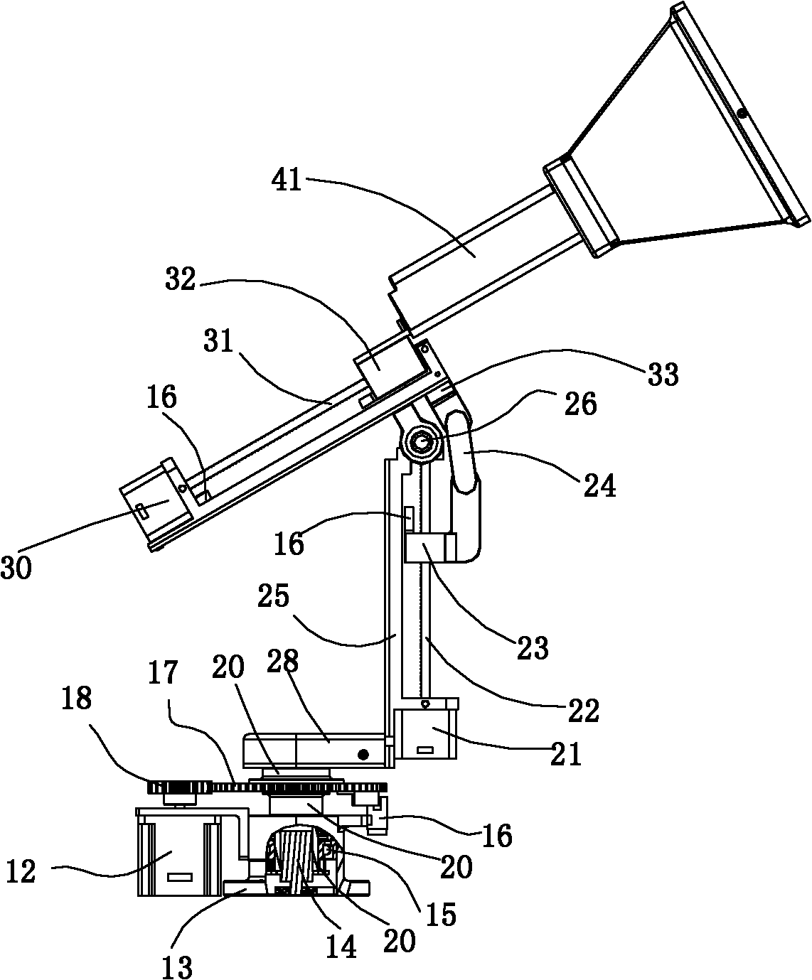
The invention discloses an optics detecting device which comprises a base, a vertical slide rail, a rotating slide rail and a visual probe; the base is provided with a first driving mechanism which is connected with the bottom of the vertical slide rail and drives the vertical slide rail to rotate horizontally around the vertical axis of the base; the vertical slide rail is provided with a second driving mechanism which is connected with the rotating slide rail and drives the rotating slide rail to rotate around the transverse axis at the upper end of the vertical slide rail; the rotating slide rail is provided with a third driving mechanism which is connected with one end of the visual probe and drives the visual probe to move along the axis of the rotating slide rail in parallel. In the invention, flare information incident from any angle can be captured by using a single sampling surface, no detection blind area exists in the hemisphere range, thus the device facilitates the detection work greatly. The space linear equation of a beam central axis can be constructed without moving the detecting device, improving the detecting accuracy. The device is low in weight, small in size and has short detection time and is particularly suitable for optics positioning detection of medical radiation and a radiotherapy device.
Description
technical field [0001] The invention relates to an optical detection device, in particular to an optical detection device for detecting the vector directions of several light beams in space and the shape of light spots at a certain spatial position. Background technique [0002] Many large-scale equipment need to use beams to simulate their own positioning coordinate system in space, and determine the spatial position of the origin of coordinates by crossing beams, so as to ensure the accuracy and precision of other related supporting equipment in spatial positioning and relative movement. Especially, in the field of medical radiation inspection and radiation therapy, radiation inspection equipment (such as: CT, x-ray simulation positioning machine, etc.) etc.) use the three-dimensional laser positioning lamp to fit the treatment central axis and spatial positioning coordinate system of these devices in space, and use the spot position and shape irradiated by the field simul...
Claims
Login to View More Application Information
Patent Timeline
 IPC IPC(8): G01B11/24G01C1/00A61B6/00A61N5/00
Inventor杨诚
Owner深圳市华盼科技有限公司