Roughness detection robot for precision machining and detection method thereof

A technology of precision machining and roughness, which is applied in the field of precision machining roughness detection robot and its detection. The effect of precision

Inactive Publication Date: 2019-11-26
NANJING HANXIYUE AUTOMATION TECH CO LTD
View PDF11 Cites 4 Cited by
  • Summary
  • Abstract
  • Description
  • Claims
  • Application Information

AI Technical Summary

Problems solved by technology

At present, there are generally separate hand-held roughness meters and a complete set of fixed roughness measuring instruments on the market. High, not conducive to cost saving, for this reason urgently need to solve the above technical problems
[0003] Chinese patent (authorized announcement number: CN202361976U) discloses a roughness detection device, which is only a single-point adjustment through a rectangular screw rod, and can only perform single-point roughness detection, which is not suitable for precision machining operations field

Method used


Image

  • Roughness detection robot for precision machining and detection method thereof
  • Roughness detection robot for precision machining and detection method thereof
  • Roughness detection robot for precision machining and detection method thereof

Examples


Embodiment 1

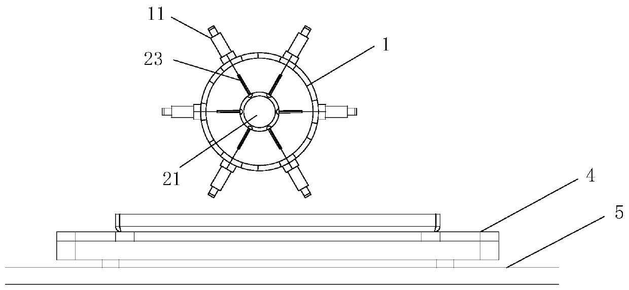
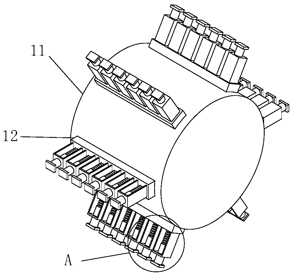
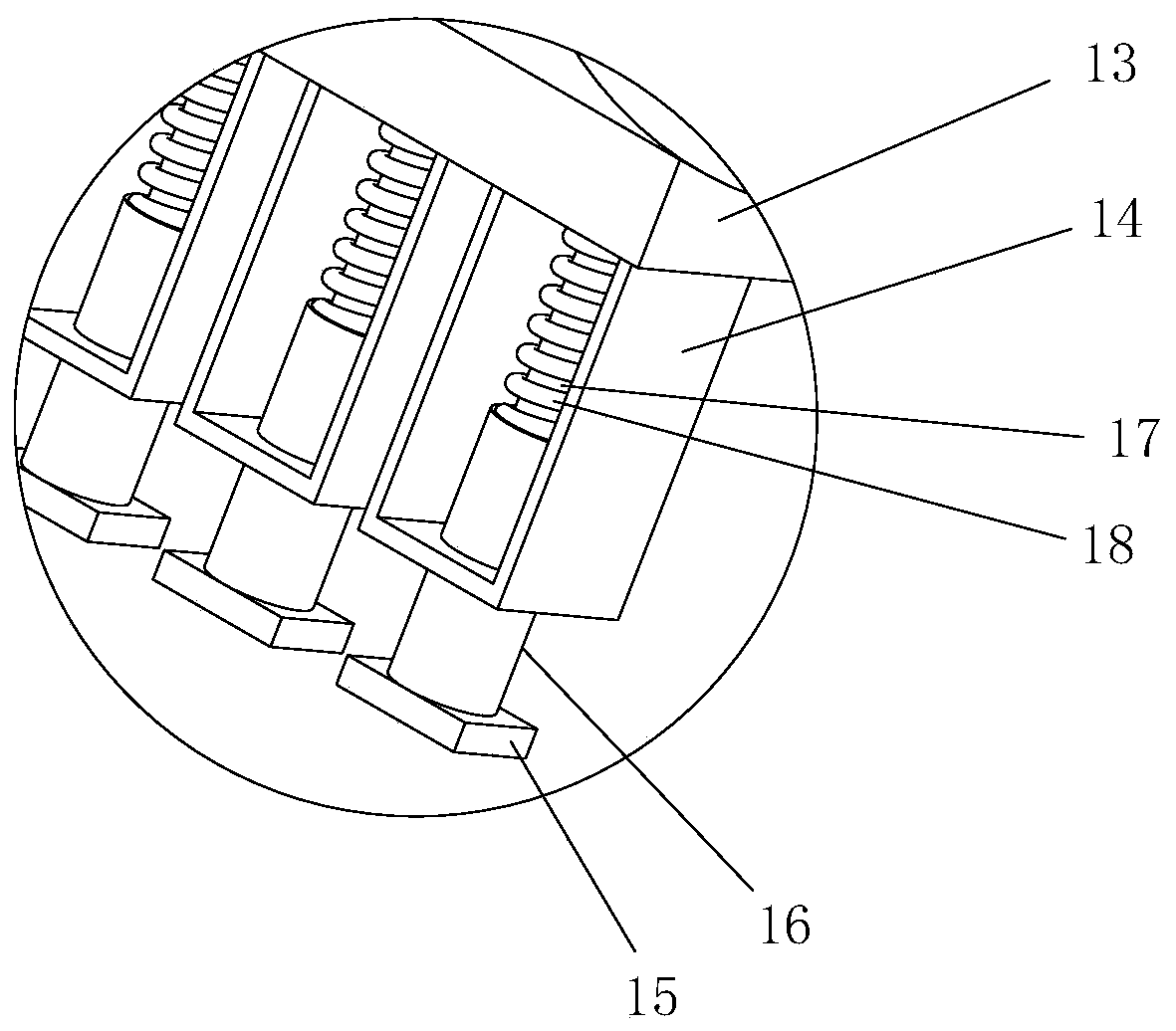
[0032] see figure 1 , figure 2 and image 3 , a roughness detection robot for precision machining, comprising a transmission frame 2 and a conveyor belt 5, the conveyor belt 5 is provided with a bearing jig 4, the transmission frame 2 is equipped with a detection mechanism 1, and the detection The main body of the mechanism 1 is a detection barrel 11, the detection barrel 11 is a cylindrical structure, and several detection frames 12 are equidistantly installed on the outer wall of the detection frame 11, and the detection frames 12 pass through the fixed substrate 13 is installed on the outer wall of the detection machine barrel 11. Several detection brackets 14 are independently arranged on the detection frame 12. The front end of the detection bracket 14 is equipped with a detection head 15, and the detection head 15 is inserted through the movable sleeve 16. Installed on the detection bracket 14, the inner cavity of the detection bracket 14 is provided with a fixed rod ...

Embodiment 2

[0037]Please refer to Fig. 5, the present embodiment is further optimized as embodiment one, on its basis, the both sides of described conveyor belt 5 are all equipped with supporting plate 38, and lifting frame 3 is all installed on described supporting plate 38 , the lifting guide rail 31 is installed on the lifting frame 3, the sliding seat 32 is installed on the lifting guide rail 31, the sliding seat 32 is installed on the notch of the lifting guide rail 31 through the roller 33, and the lifting frame 3 Lifting screw rods 34 are all installed, and threaded sleeves 36 are installed on the inner side of the sliding seat 32, and the lifting screw rods 34 are all pierced in the screw holes of the corresponding threaded sleeves 36, and the tops of the lifting screw rods 34 are equipped with transmission The wheel 35 is connected by a synchronous belt 37 between the transmission wheels 35 on both sides.

[0038] The application is provided with a lifting frame 3 to drive the tr...

Embodiment 3

[0040] see Figure 6 , this embodiment is further optimized as Embodiment 1. On the basis of it, a leveling mechanism 41 is installed on the bottom of the carrying jig 4, and bending frames 42 are installed at the four corners of the leveling mechanism 41. The four corners of the carrying fixture 4 are provided with corresponding support rods 43, and the support rods 43 are installed on the corresponding bending frame 42 through the movable shaft 44, and the angle measuring instrument 45 is installed on the bending frame 42, The angle measuring instrument 45 is provided with arc-shaped grooves 46 , and balls 47 are installed on the support rods 43 , and the balls 47 are embedded in the notches of the corresponding arc-shaped grooves 46 . Bending struts 48 are also installed at the four corners of the carrying jig 4 and the leveling mechanism 41 .

[0041] In view of the different shapes of the workpieces, and the inspection surface is not normally on the horizontal line, the ...


PUM


Abstract

The invention relates to the field of precision machining processes, and specifically relates to a roughness detection robot for precision machining and a detection method thereof. The roughness detection robot comprises a transmission frame and a material conveying belt, wherein the transmission frame is equipped with a detection mechanism, the main body of the detection mechanism is a detectionmachine barrel, and the outer barrel wall of the detection machine barrel is equipped with a plurality of detection frames at equal intervals, each detection frame is mounted on the outer wall of thedetection machine barrel through a fixed base plate, a plurality of detection brackets are independently arranged on each detection frame, the front end of each detection bracket is equipped with a detection head, each detection head is installed on the detection bracket in a penetrating mode through a movable sleeve, the inner cavity of the detection bracket is provided with a fixed rod, the movable sleeve is arranged on the fixed rod in a sleeving mode, each fixed rod is wound with an extrusion spring, a plurality of elasticity detectors are arranged in the detection machine barrel, and theextrusion springs are respectively connected with the elastic detectors. According to the invention, the surface is converted into points on the whole during the detection, and then the points are integrated into the surface, thereby achieving the effects of high-efficiency operation and high-efficiency analysis.

Description

technical field [0001] The invention relates to the field of precision machining technology, in particular to a roughness detection robot for precision machining and a detection method thereof. Background technique [0002] In order to detect the surface roughness of the workpiece, we need special roughness detection equipment. At present, there are generally separate hand-held roughness meters and a complete set of fixed roughness measuring instruments on the market. High, unfavorable for saving cost, need to solve above-mentioned technical problem urgently for this reason. [0003] Chinese patent (authorized announcement number: CN202361976U) discloses a roughness detection device, which is only a single-point adjustment through a rectangular screw rod, and can only perform single-point roughness detection, which is not suitable for precision machining operations field. Contents of the invention [0004] The object of the present invention is to provide a roughness de...

Claims


Application Information

Patent Timeline
IPC IPC(8): G01B21/30B25J11/00
CPCB25J11/00G01B21/30
Inventor 张娟娟苏艺鑫
Owner NANJING HANXIYUE AUTOMATION TECH CO LTD
Why Eureka
Try Eureka