
On-chip clock uncertainty measurement circuit device and system

A technique for measuring uncertainty and measuring circuits, which is applied in the field of measuring the uncertainty of chip clocks. It can solve the problems of large data volume circuit scale, process dependence, and large noise, and achieve less control data, large measurement range, and high measurement accuracy. Effect

Active Publication Date: 2013-05-01
LOONGSON TECH CORP
View PDF11 Cites 3 Cited by
  • Summary
  • Abstract
  • Description
  • Claims
  • Application Information

AI Technical Summary

Problems solved by technology

However, this method needs to store and calculate a large amount of data, and at the same time needs to introduce another frequency clock, which is very difficult in practice, so there is no large-scale industrial application at present
[0010] After analysis, it is found that these existing technologies mainly use a single linear delay method to adjust the clock. The main problem they face is that the measurement range and measurement accuracy are small, and the amount of data to be processed and the required circuit scale are also relatively large. Big
Also, longer delay lines introduce more noise
And for a circuit like SKITTER, it is too dependent on the process, and it needs to use a specific process to achieve its measurement accuracy, which is not universal

Method used


Image

  • On-chip clock uncertainty measurement circuit device and system
  • On-chip clock uncertainty measurement circuit device and system
  • On-chip clock uncertainty measurement circuit device and system

Examples


Embodiment Construction

[0041] In order to make the purpose, technical solution and advantages of the present invention clearer, the measurement circuit device and system with uncertain on-chip clock of the present invention will be further described in detail below in conjunction with the accompanying drawings and embodiments. It should be understood that the specific embodiments described here are only used to explain the present invention, not to limit the present invention.

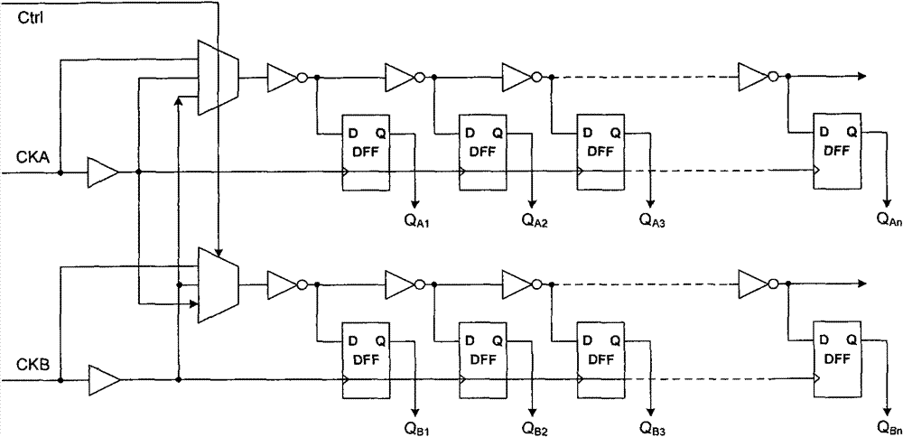
[0042] The on-chip clock uncertainty measurement circuit device and system of the embodiments of the present invention utilize the principle of a delay-locked loop (Delay-Locked Loop). The on-chip clock uncertainty measurement system of the embodiment of the present invention includes two parts: an on-chip clock uncertainty measurement circuit device 1 (Skew and Jitter Measurement, SJM); and a scale circuit (Ring).

[0043] Wherein, the on-chip clock uncertainty measurement circuit device is used to measure the clock skew an...


PUM


Abstract

The invention provides an on-chip clock uncertainty measurement circuit device. The device comprises a delay circuit and a detection unit, wherein the delay circuit comprises a rough adjustment circuit and a fine adjustment circuit; two paths of clock signals A and B to be measured from two different measurement points of the same time source on a chip are roughly adjusted and delayed by the rough adjustment circuit; the roughly adjusted clock signals A and B are finely adjusted and delayed by the fine adjustment circuit; the phases of the finely adjusted clock signals A and B are detected bythe detection unit; and the clock skew of the clock signals A and B is calculated when the phases of the finely adjusted clock signals A and B are the same. The invention also provides a measurement system which comprises the measurement circuit device and a ruler circuit. In the invention, on-chip measurement is performed on the clock skew and even clock jitter by using a composite non-linear delay line, so the measurement accuracy is high and the required data quantity is small.

Description

technical field [0001] The invention relates to the technical field of measurement of chip clock uncertainty, in particular to an on-chip measurement circuit device and system of a microprocessor capable of measuring clock deviation or even clock jitter. Background technique [0002] Computers today use clocks a lot, for example, to make sure that many operations happen in the correct order or in sync. Therefore, it is important that the clocks themselves operate close to synchronously. Typically, the two clocks are not perfectly synchronized and there are timing differences between the clocks. Additionally, the timing difference between the two clocks varies over time. This change in clock timing difference is known as clock skew or clock skew. Many computer timing protocols require information such as the time offset between two clocks. [0003] On-Chip Clock Uncertainty Measurement (On-Chip Clock Uncertainty Measurement) system is suitable for processing a large amoun...

Claims


Application Information

Patent Timeline
Patent Type & Authority Patents(China)
IPC IPC(8): G01R31/317
Inventor 于航杨旭
Owner LOONGSON TECH CORP
Learn More