Passive optical network and protection switching method thereof

A passive optical network and protection switching technology, which is applied in the communication field, can solve the problems of complex process, slow recovery speed, poor applicability, etc., and achieve the effect of simplifying the switching process and reducing the switching time

Inactive Publication Date: 2011-05-25
ZTE CORP
View PDF3 Cites 16 Cited by
  • Summary
  • Abstract
  • Description
  • Claims
  • Application Information

AI Technical Summary

Problems solved by technology

[0013] The technical problem to be solved by the present invention is to provide a passive optical network (Passive Optical Network, referred to as PON) and its protection

Method used


Image

  • Passive optical network and protection switching method thereof
  • Passive optical network and protection switching method thereof
  • Passive optical network and protection switching method thereof

Examples


Example Embodiment

[0043] Example 1:

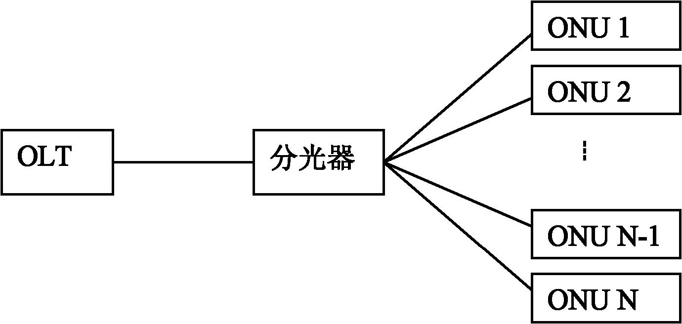
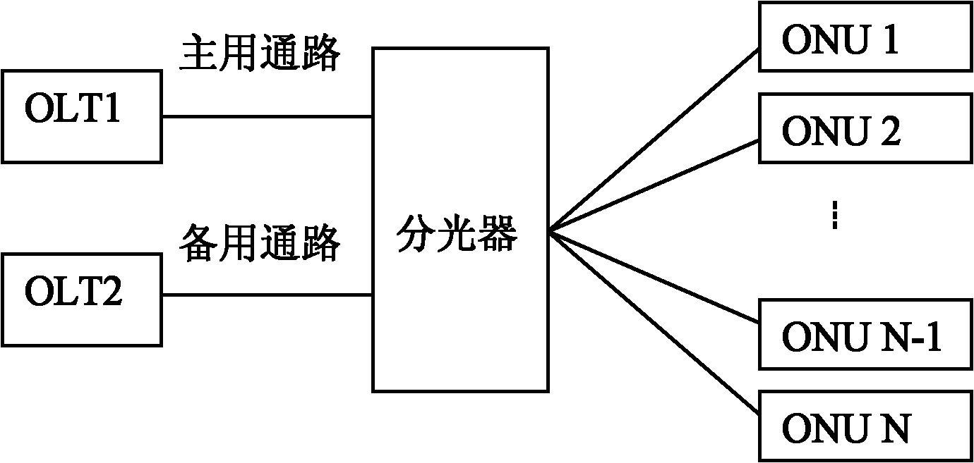
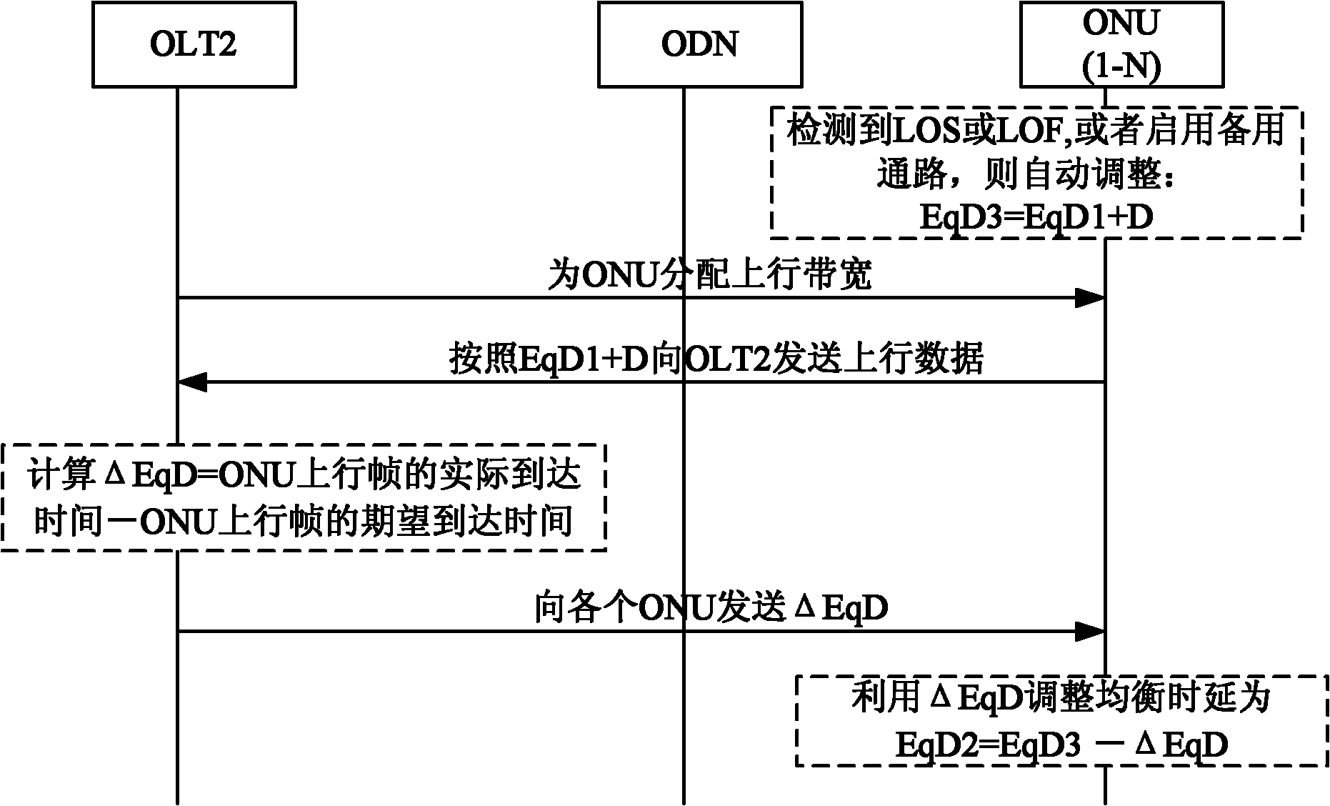
[0044] Such as figure 2 As shown, in the topology of the passive optical network protecting the backbone fiber mode, the path from the first optical line terminal OLT1 to the ONU through the splitter is the main path, and the second optical line terminal OLT2 reaches the ONU through the splitter. The path is a spare path. The primary channel serves as the service channel for the optical network unit and the optical line terminal. After the primary channel is interrupted, if the optical network unit ONU detects signal loss or frame loss (LOS or LOF), or the standby channel is immediately activated to keep the light For the communication between the network unit and the optical line terminal, after the ONU detects the downstream optical signal of the OLT2, the ONU and the OLT use signaling interaction to complete the update of the ONU's equalized delay (EqD) value, such as image 3 Shown.

[0045] If the ONU detects signal loss or frame loss (LOS or LOF), or det...

Example Embodiment

[0054] Example two

[0055] Such as Figure 4 As shown, the protection switching method in the passive optical network of the present invention includes the following steps:

[0056] Step 401: All ONUs automatically adjust their own EqD values, and the updated EqD value of the ONU is equal to the value EqD1 before the ONU update plus the delay constant D (D>0, preferably D≥250us);

[0057] Step 402: OLT2 continues to allocate upstream bandwidth to each ONU according to the method of the prior art;

[0058] Step 403: The ONU sends uplink data according to the updated equalization delay EqD1+D within the uplink bandwidth allocated to itself by the OLT2, so as to achieve uplink data synchronization;

[0059] Step 404: After receiving the uplink frame sent by the ONU, the OLT2 calculates the equalization delay adjustment value ΔEqD that the ONU needs to adjust according to the following method, and sends the ΔEqD to all ONUs;

[0060] Among them: ΔEqD = actual arrival time of ONU upstream f...


PUM


Abstract

The invention relates to the technical field of communication and discloses a passive optical network and a protection switching method thereof. In the invention, when an optical network unit (ONU) detects the loss of downlink signals, the loss of downlink frames, or the generation of main/standby protection switching, the balance delay value stored by the ONU is increased; additionally, after the balance delay value of the ONU is increased, the ONU sends uplink data in the uplink bandwidth allocated by an optical line terminal (OLT); after receiving the uplink data sent by the ONU, the OLT calculates the balance delay adjustment value of the ONU and sends the balance delay adjustment value to all the ONUs; and the ONUs respectively correct the current balance delay values according to the balance delay adjustment value. By using the invention, the communication between the OLT and the ONUs after the protection switching can be quickly established, thereby simplifying the switching process of the ONUs under the protection mode and shortening the switching time.

Description

technical field [0001] The present invention relates to the communication field, in particular to a passive optical network (Passive Optical Network, PON for short) and a protection switching method thereof. Background technique [0002] Gigabit-Capable Passive Optical Network (GPON) technology is an important technical branch of the passive optical network (PON) family, similar to other PON technologies, GPON is also a point-to-multipoint Topological passive optical access technology. The topology of GPON system is as follows: figure 1 As shown, the GPON system consists of an optical line terminal (Optical Line Terminal, OLT for short), an optical network unit (Optical Network Unit, ONU for short) at the user side, and an optical distribution network (Optical Distribution Network, ODN for short). , usually using a point-to-multipoint network structure. The optical distribution network ODN is composed of passive optical devices such as single-mode optical fibers, optical ...

Claims


Application Information

Patent Timeline
IPC IPC(8): H04B10/00H04B10/08H04J3/06H04B10/032H04B10/272
CPCH04B10/272H04Q2011/0081H04Q11/0067H04B10/032
Inventor 张伟良耿丹
Owner ZTE CORP
Why Eureka
Try Eureka