
Optical call column for railway section

A technology for optical calls and railways, applied in optical fiber transmission, electromagnetic wave transmission systems, electrical components, etc., can solve problems such as insufficient communication capabilities, difficult maintenance, and large losses, and achieve stable and reliable access and transmission, and convenient installation and maintenance , Use safe and stable effect

Inactive Publication Date: 2011-05-25
成都华铁电子技术发展有限公司
View PDF4 Cites 4 Cited by
  • Summary
  • Abstract
  • Description
  • Claims
  • Application Information

AI Technical Summary

Problems solved by technology

The use of copper core long-distance symmetrical cables to transmit telephone voice information has narrow bandwidth, small capacity, large loss, poor resistance to electrical interference, difficult maintenance, high construction and maintenance costs, single business types, and communication capabilities that do not meet the needs of transportation to communication transmission. It cannot adapt to the requirements of the development of railway modernization for inter-section communication, multi-channel signals, and multi-service access transmission.

Method used


Image

  • Optical call column for railway section
  • Optical call column for railway section
  • Optical call column for railway section

Examples


specific Embodiment approach

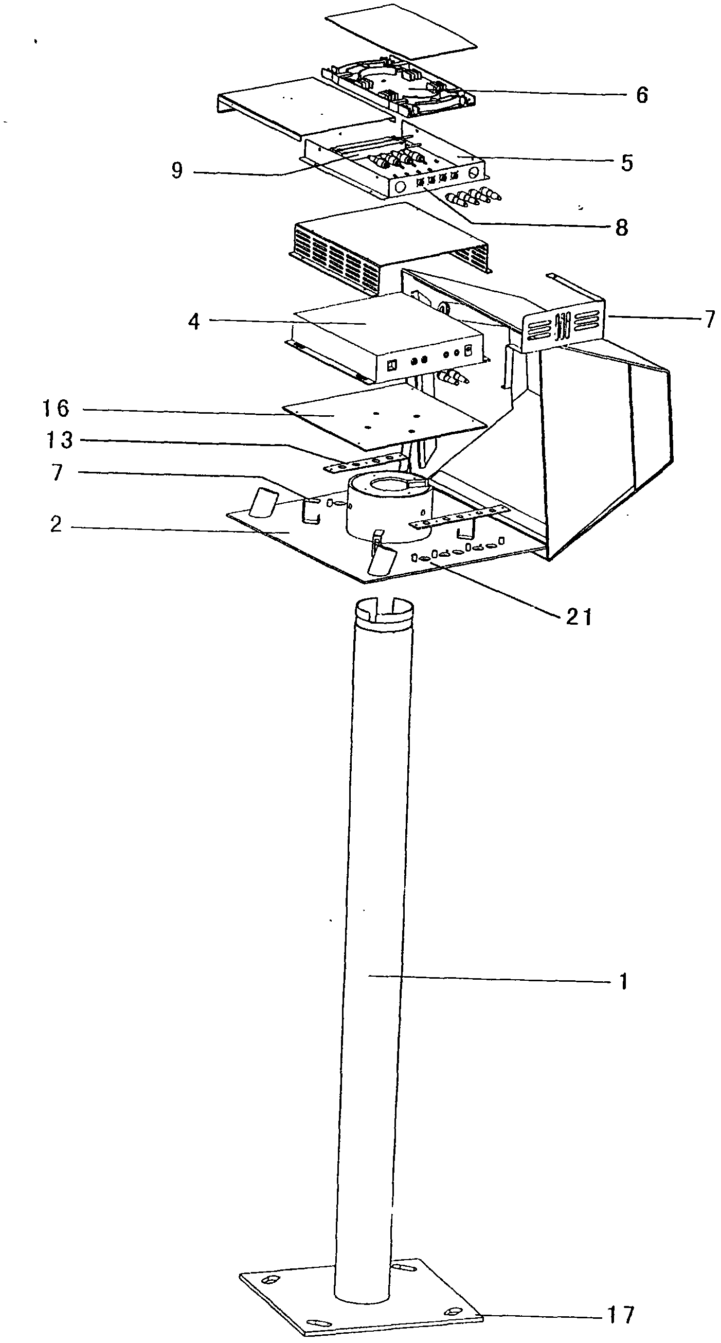
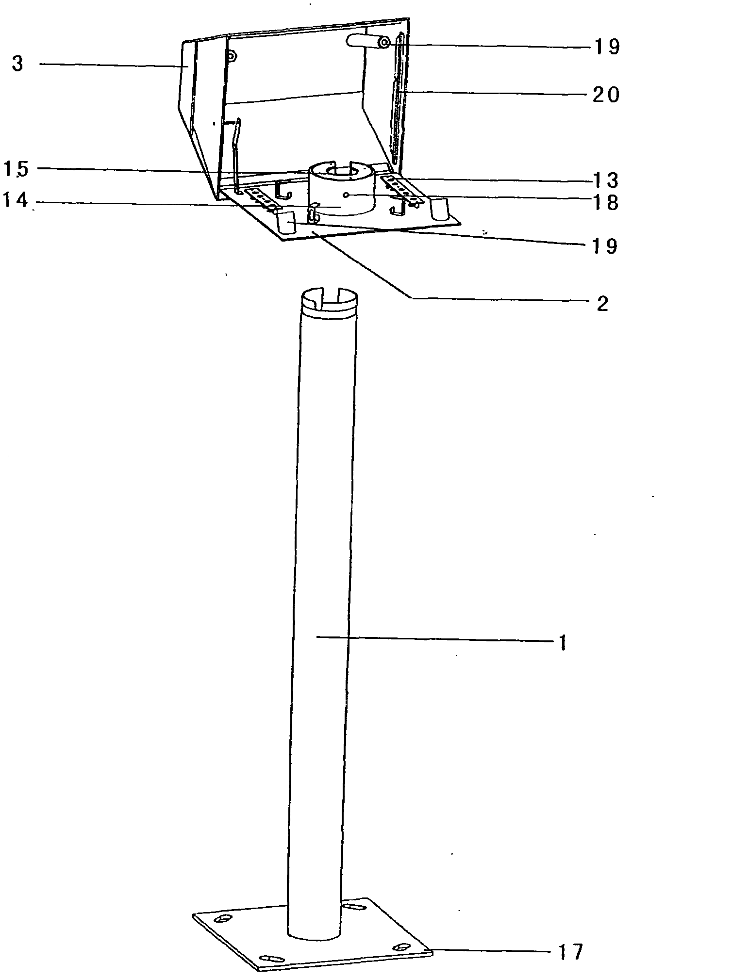
[0026] detailed description: , the hollow column 1 and the top box are connected; and the top box is composed of the top box cover 3 and the bottom plate 2 of the top box, and there are pipe sleeves 14 on the top box bottom plate 2, and pipe sleeves 14 The hollow column 1 is tightly connected by three fixing bolts 18 at an angle of 120 degrees on three horizontal planes, which have the function of anti-theft and anti-prying. A sealing ring 20 is installed on the inner peripheral edge of the column top box cover 3 for sealing effect; inside the column top box box there are optical fiber introduction fusion splicing wiring unit 6, optical fiber coupling splitter unit 5, inter-area optical remote equipment 4 and bottom plate 2 , the base plate 2 has a distribution port plate 13 and a socket output port 21 . Its working principle is that the communication optical cable or cable is introduced into the post-top box through the hollow channel of the hollow base fixing plate 17 of t...


PUM


Abstract

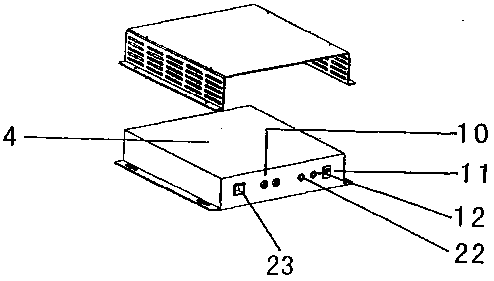
The invention discloses an optical call column for a railway section to solve the problem of point-to-multipoint optical communication transmission access in the railway section. An upper end of a hollow column (1) is connected with a base plate; an optical cable or an electric cable enters a cavity through the hollow column (1) and is divided into an optical fiber bundle tube or an electric cable core wire; and the optical fiber bundle tube or the electric cable core wire is fixedly connected with a fixing bracket (7) on the base plate (2). The optical fiber bundle tube enters an optical fiber lead-in welding layout unit (6) and is connected with the same; upper and lower link through fiber pigtails led out of the optical fiber lead-in welding distribution unit (6) are connected in series with an optical adapter (8) on an optical fiber coupling divider unit (5); the optical adaptor (8) is connected with an optical splitter (9) which is connected with an optical transceiver interface (10) of section optical far-end equipment (4); a power interface (11) and a telephone interface (22) of the section optical far-end equipment (4), an Ethernet port (23) and an E1 interface (12) are connected with a distribution port plate (13) on the base plate (2); and the electric cable core wire is connected with the distribution port plate (13) on the base plate (2).

Description

technical field [0001] The present invention relates to the optical fiber communication device in the railway section. Background technique [0002] Interval communication is an important part of railway special communication system. The traditional inter-section communication is an analog system, and only one voice signal can be transmitted on a pair of copper core cables. As far as emergency communication is concerned, several pairs of copper core cables are needed to realize simple multi-channel voice communication. The use of copper core long-distance symmetrical cables to transmit telephone voice information has narrow bandwidth, small capacity, large loss, poor resistance to electrical interference, difficult maintenance, high construction and maintenance costs, single business types, and communication capabilities that do not meet the needs of transportation to communication transmission. It cannot adapt to the requirements of the development of railway modernization...

Claims


Application Information

Patent Timeline
Patent Type & Authority Applications(China)
IPC IPC(8): H04B10/14H04B10/25
Inventor 刘新田朱小敏邵兵
Owner 成都华铁电子技术发展有限公司
Learn More