Method for multistage sampling of floating-roof oil tank

A technology of oil storage tanks and floating roofs, which is applied in the direction of sampling devices, etc., to achieve the effect of reducing sampling procedures, reducing labor intensity, and convenient sampling

Inactive Publication Date: 2011-06-01
CHINA PETROLEUM & CHEM CORP +1
View PDF6 Cites 12 Cited by
  • Summary
  • Abstract
  • Description
  • Claims
  • Application Information

AI Technical Summary

Problems solved by technology

[0003] The purpose of the present invention is to provide a method for multi-stage sampling of floating roof oil storage tanks, which overcomes the above-mentioned defects of manual sampling

Method used


Image

  • Method for multistage sampling of floating-roof oil tank
  • Method for multistage sampling of floating-roof oil tank

Examples


Embodiment Construction

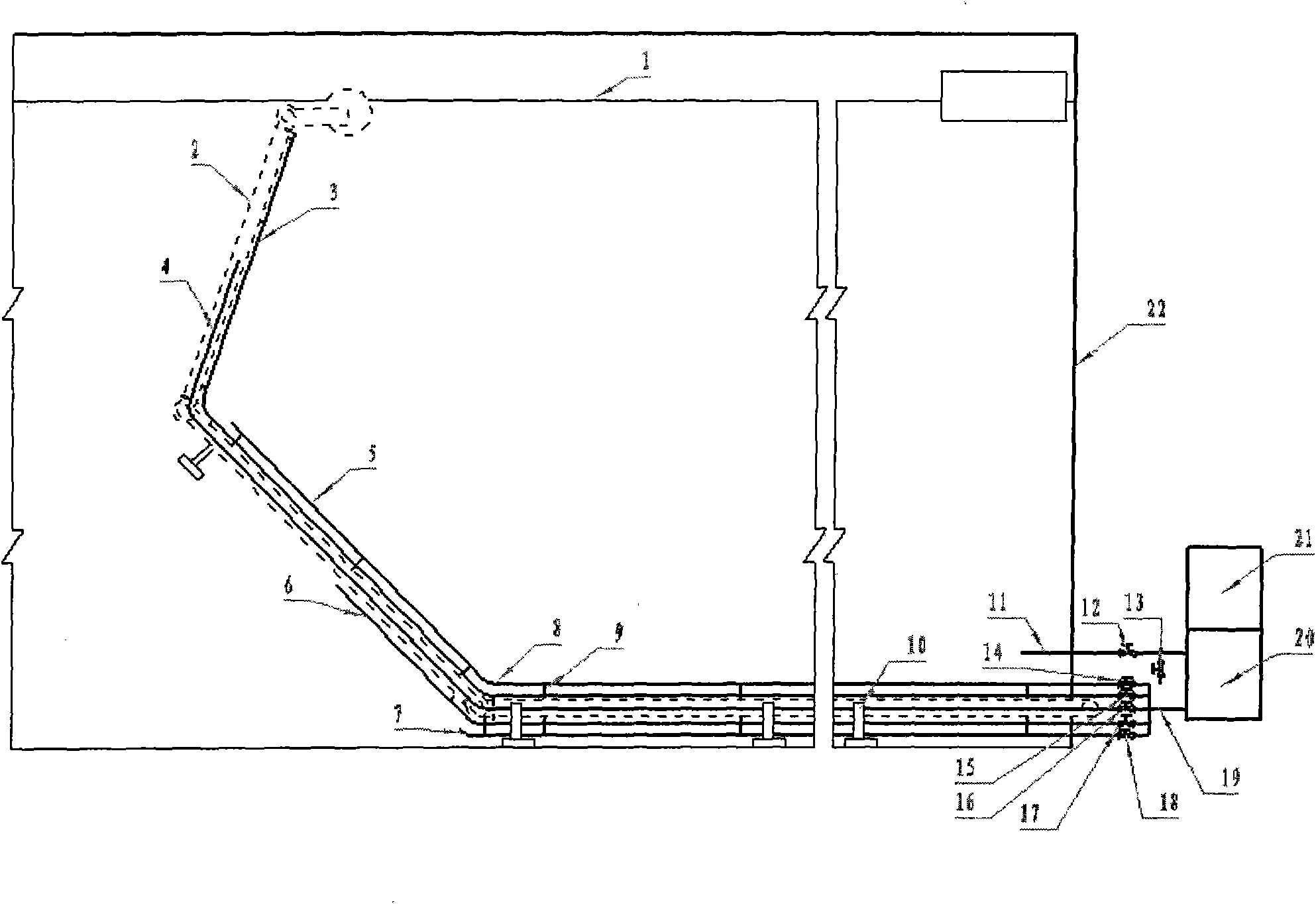
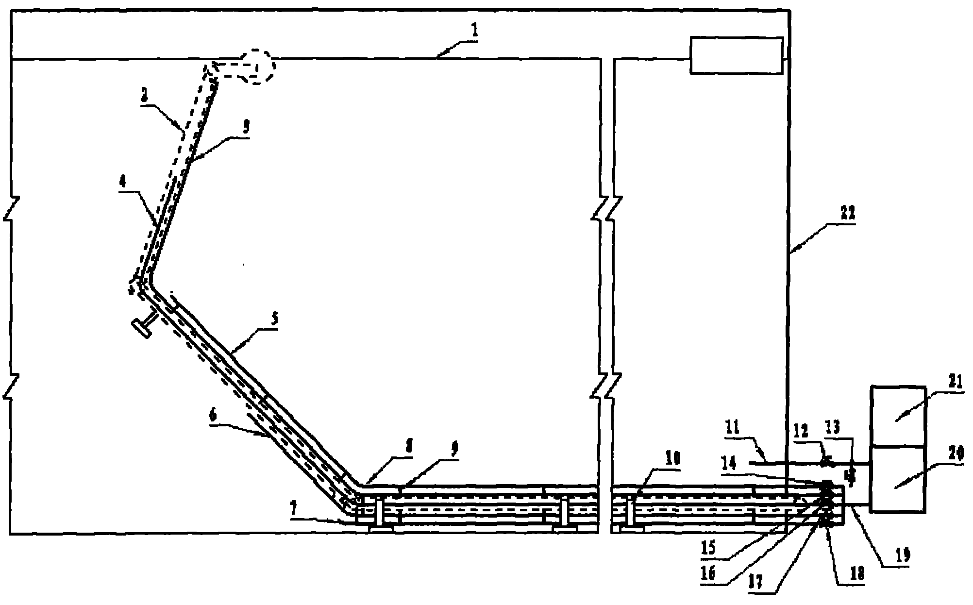
[0013] In order to further disclose the technical solutions of the present invention, the following will be described in detail through examples in conjunction with the accompanying drawings:

[0014] Design an upper sampling pipe with a diameter of 15-20mm from the upper part, upper middle part, middle part, middle lower part and lower part of the central drainage pipe 2 of the floating roof oil storage tank to the lower side of the same side of the floating roof oil storage tank 1 3. The upper and middle sampling tube 4, the middle sampling tube 5, the middle and lower sampling tube 6 and the lower sampling tube 7, connect the ends of the above sampling tubes 3, 4, 5, 6, and 7 in parallel with the ycd0.6-0.6 The gear pump inlet pipes of the gear pump 20 are connected, and a sampling control valve 14, 15, 16, 17, 18 is respectively designed on the pipeline before parallel connection; 22, the lower part is connected, and the gear pump outlet control valve 12 and sampling valve...


PUM


Abstract

The invention discloses a method for the multistage sampling of a floating-roof oil tank. The method comprises the following steps of: designing an upper part sampling pipe, an upper middle part sampling pipe, a middle part sampling pipe, a lower middle part sampling pipe and a lower part sampling pipe from the upper part, the upper middle part, the middle part, the lower middle part and the lower part of the circumferential side of a central drainage pipe of the floating-roof oil tank to the outside of the lower side of the same circumferential side of the floating-roof oil tank; connecting the distal ends of the sampling pipes in parallel and then connecting with an inlet of a gear pump, and respectively designing a sampling control valve at the pipelines before being connected in parallel; connecting an outlet of the gear pump with the lower part of the floating-roof oil tank by an oil return pipe, and designing a gear pump outlet control valve and a sampling valve at the front part and the back part of the oil return pipe; and opening a gear pump inlet control valve and the gear pump outlet control valve of the upper part sampling pipe when sampling oil of the upper part of the floating-roof oil tank, starting the gear pump to firstly drain the dead oil in the sampling pipes into the floating-roof oil tank through the oil return pipe, and then opening the sampling valves to sample, wherein the sampling process of each part is same. The method of the invention is convenient to the multistage sampling of the floating-roof oil tank and also saves time and labor.

Description

technical field [0001] The invention relates to a multi-stage sampling method for an oil storage tank with a floating roof, which meets the requirements of China Petrochemical Co., Ltd. for sampling and analyzing oil products in the oil storage tank. Background technique [0002] According to the national standard of the People's Republic of China (CB / T4756-1998) petroleum liquid manual sampling method, in the third-level sampling of floating roof oil storage tanks, it is necessary to climb to the top of the tank with a height of more than ten meters, and then go down to the floating roof along the escalator inside the tank. Top middle, hand sampled. Not only does the sampling need to be repeated three times, but also the sampling process is very strict; especially now that Sinopec requires five-level and six-level sampling to strengthen the analysis of oil quality, the sampling task is even more arduous. At the same time, it is unavoidable that some oil products will be sp...

Claims


Application Information

Patent Timeline
Patent Type & Authority Applications(China)
IPC IPC(8): G01N1/14
Inventor 付庆祥张好民董连杰李长友缪清朝李凤乾何晓辉盖永军石崇硕段晓燕闫滨张崟王晓丽
Owner CHINA PETROLEUM & CHEM CORP
Why Eureka
Try Eureka