Sensor device, driving method, display device, electronic unit and image pickup device

A sensor device and sensor element technology, applied in the fields of sensor devices, drives, display devices, electronic units and camera devices, can solve problems such as inability to reset charges, achieve stable detection operations and reduce afterimages

Active Publication Date: 2011-06-01
JAPAN DISPLAY INC
View PDF8 Cites 27 Cited by
  • Summary
  • Abstract
  • Description
  • Claims
  • Application Information

AI Technical Summary

Problems solved by technology

Specifically, there is a problem that even when a reset voltage is supplied in a short period of time after the i layer enters the storage state, the charge accumulated in the storage capacitance cannot be sufficiently reset.

Method used


Image

  • Sensor device, driving method, display device, electronic unit and image pickup device
  • Sensor device, driving method, display device, electronic unit and image pickup device
  • Sensor device, driving method, display device, electronic unit and image pickup device

Examples


no. 1 approach

[0069] Overall structure of display device with input function

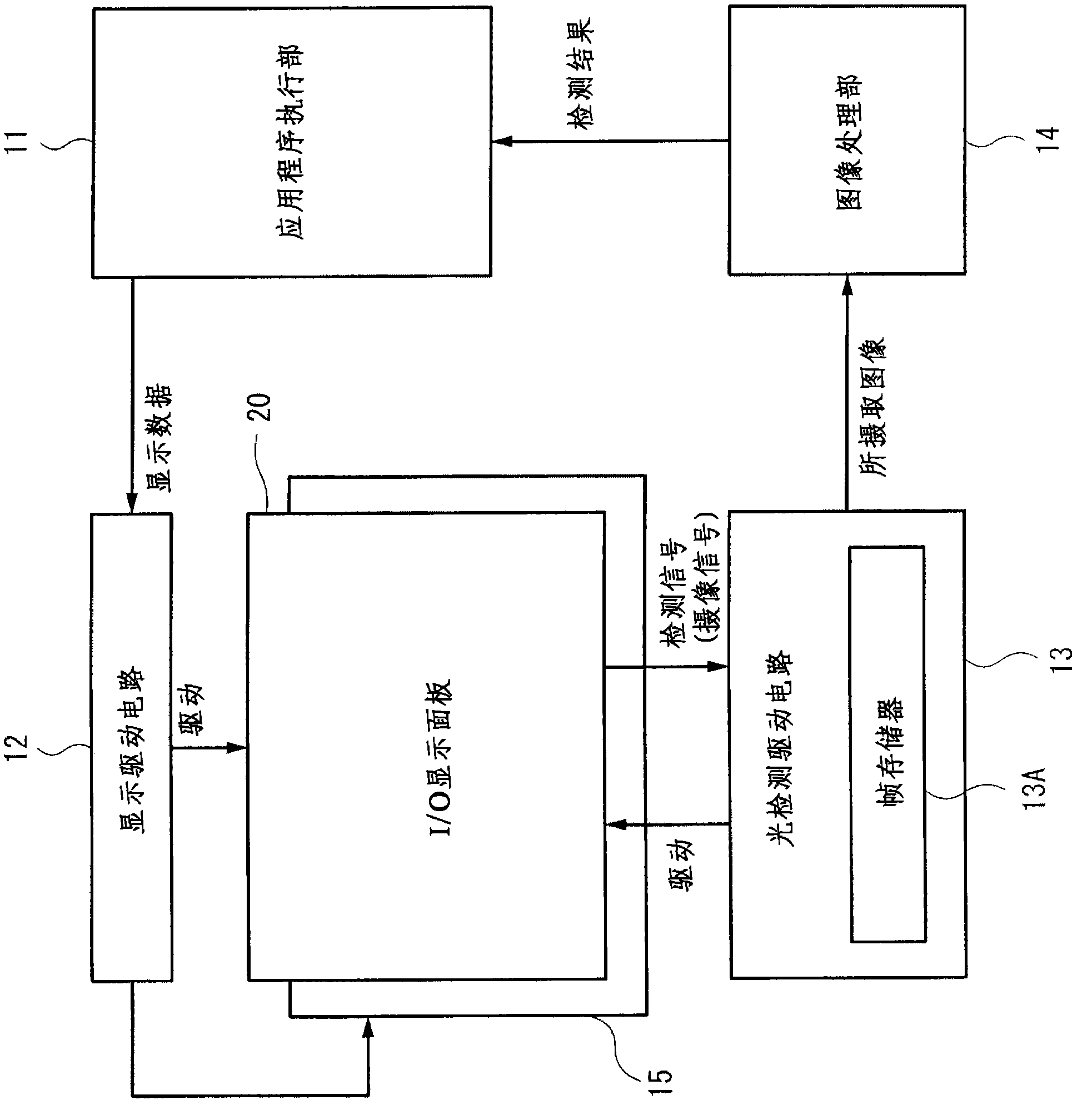
[0070] figure 1 An example of the overall structure of the display device (display camera device) with an input function of the first embodiment of the present invention is shown. This display device includes an I / O display panel 20 , a backlight 15 , a display drive circuit 12 , a light reception drive circuit (light detection drive circuit) 13 , an image processing unit 14 , and an application execution unit 11 .

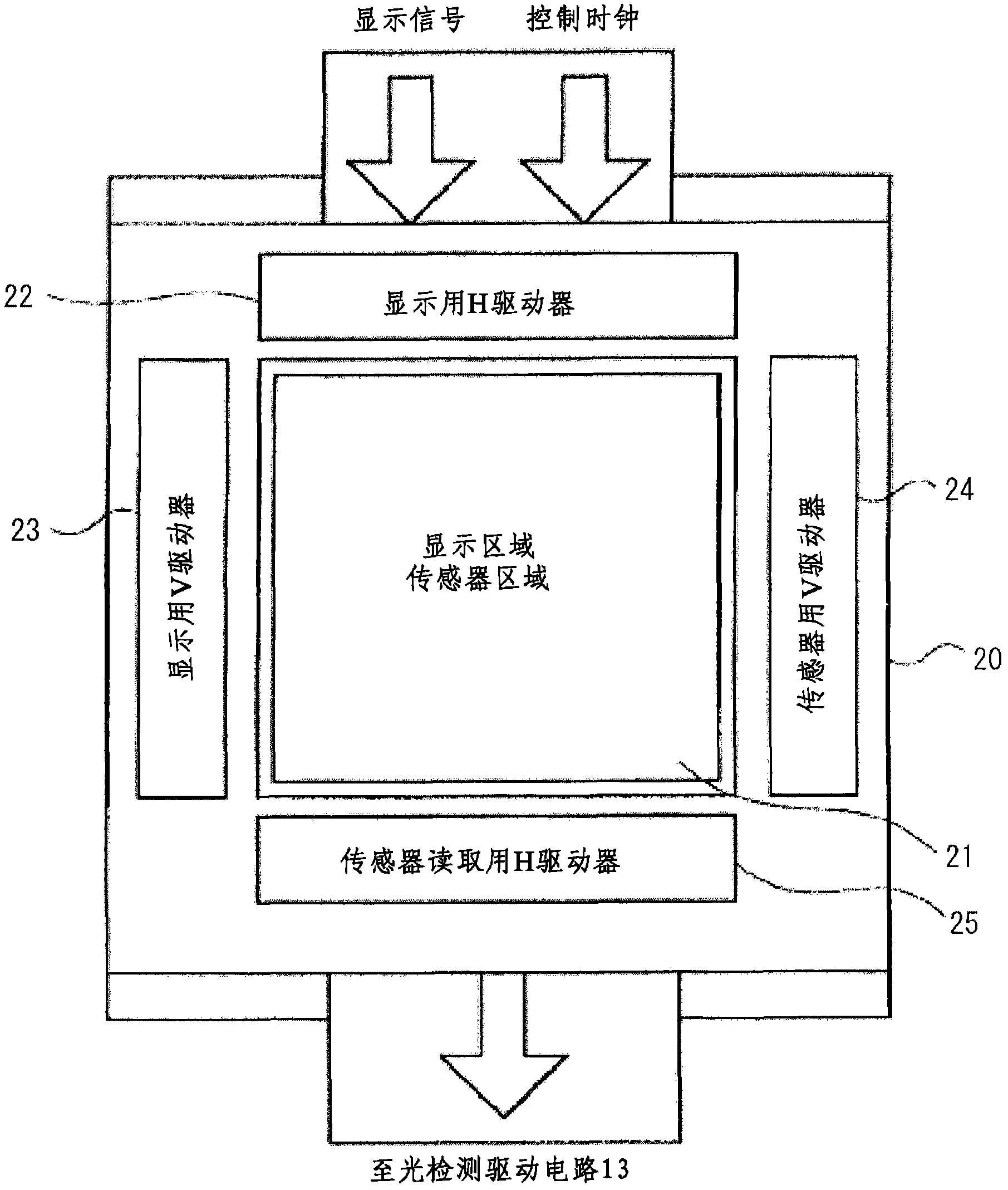
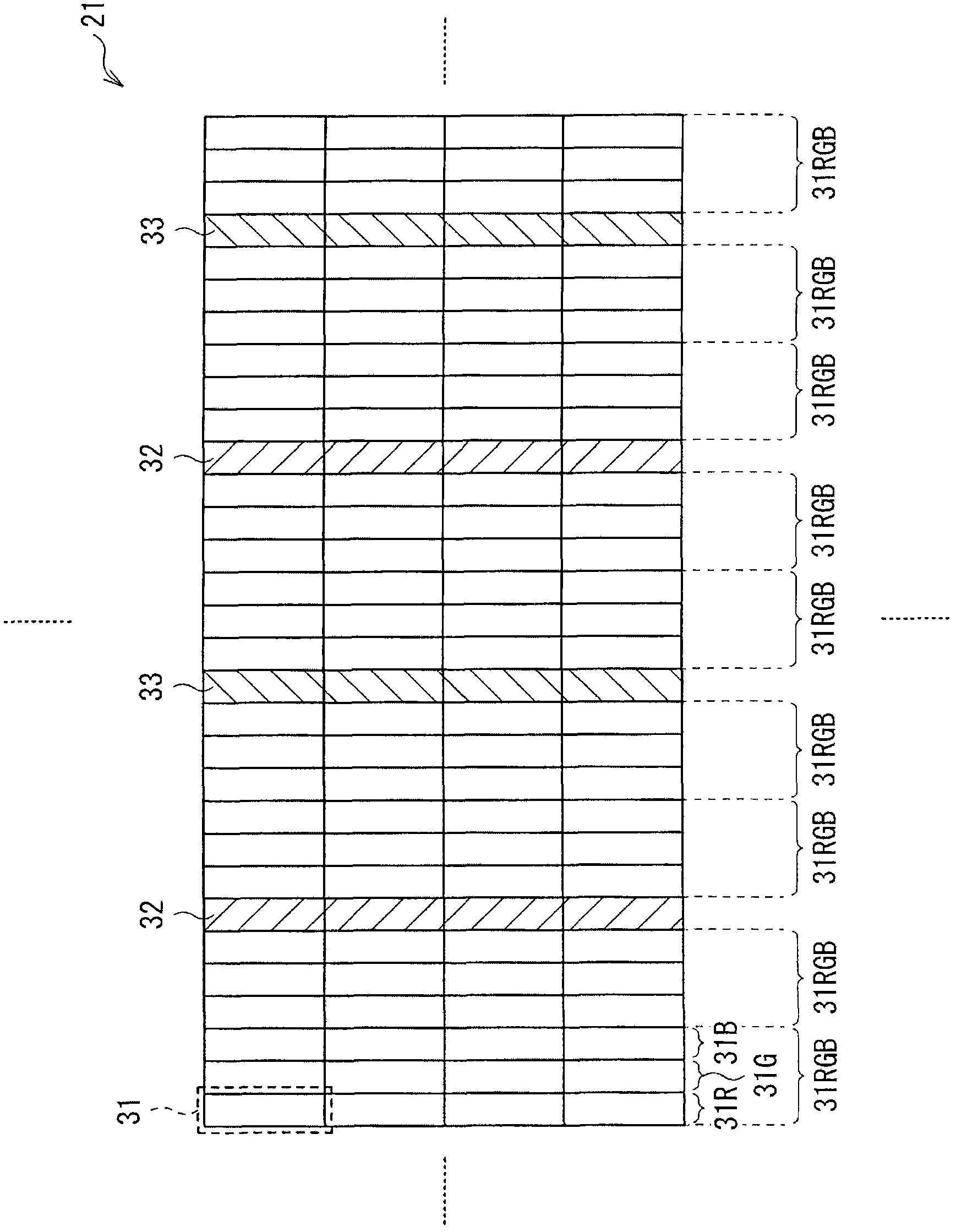
[0071] The I / O display panel 20 is, for example, a liquid crystal display (Liquid Crystal Display; LCD) panel. I / O display panel 20 includes such as image 3 A plurality of display pixels 31RGB arranged in a matrix are shown (to be described later), and have a function (display function) of displaying predetermined images such as graphics and characters based on image data while performing a line-sequential operation. The I / O display panel 20 also includes image 3 Shown (to be described later) a...

no. 2 approach

[0165] The overall structure of the radiation imaging device

[0166] In the second embodiment, a configuration example in which the present invention is applied to a radiation imaging device will be described. Figure 24 The system configuration of the photoelectric converter 102 included in the radiation imaging device 101 of the present embodiment is shown. Such as Figure 25 As shown, the radiation imaging device 101 is provided with a wavelength converter 140 on the photoelectric converter 102 . The radiation imaging device 101 reads information from radiation by converting the wavelength of radiation represented by α-rays, β-rays, γ-rays, and X-rays with the wavelength converter 140 .

[0167] The wavelength converter 140 converts the wavelength of the above radiation into a wavelength in the sensitive range of the photoelectric converter 102 . The wavelength converter 140 is a phosphor (such as a scintillator) for converting radiation such as X-rays into light having...


PUM


Abstract

The invention provides a sensor device, a driving method, a display device, an electronic unit and an image pickup device. The sensor device includes sensor elements two-dimensionally arranged and a sensor driving section driving the sensor elements. Each of the sensor elements includes a photoelectric conversion element generating electric charge according to an amount of received light, a charge storage section connected to one end of the photoelectric conversion element and storing electric charge generated by the photoelectric conversion element, a readout section reading either a voltage value resulted from the electric charge in the charge storage section or the stored electric charge, to output the read voltage value or the read electric charge and a reset section resetting the electric charge in the charge storage section through supplying a predetermined reset voltage to the charge storage section. The sensor driving section controls the reset section so that the predetermined reset voltage is continuously or intermittently supplied to the charge storage section over a period exceeding one horizontal scan period.

Description

[0001] Cross References to Related Applications [0002] This application contains subject matter related to that disclosed in Japanese Priority Patent Applications JP 2009-270424 filed on November 27, 2009, and JP 2010-225548 filed on October 5, 2010 with the Japan Patent Office, both of which The entire contents of the Japanese Priority Patent Application are incorporated herein by reference. technical field [0003] The present invention relates to a sensor device for taking an image of an object and detecting the position of an adjacent object, a method for driving a sensor element employed in such a sensor device, a display device with an input function (the display device includes a sensor function (input function) and display function), and an electronic unit including such a display device. The present invention also relates to a radiation imaging device for reading information from radiation by converting waveforms of radiation represented by α-rays, β-rays, γ-rays, ...

Claims


Application Information

Patent Timeline
Patent Type & Authority Applications(China)
IPC IPC(8): G06F3/042G09G3/36
CPCG06F3/0412G06F3/0488G06F3/042G06F3/0416
Inventor 高德真人千田满
Owner JAPAN DISPLAY INC
Why Eureka
Try Eureka